Page 1 of 1
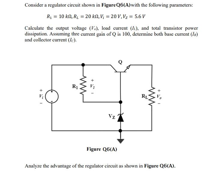
Consider a regulator circuit shown in Figure Q6(A) with the following parameters: R₁ = 10 kn, R₂ = 20 kN, V₁ = 20 V, V₂
Posted: Tue Jul 12, 2022 8:38 am
by answerhappygod
- Consider A Regulator Circuit Shown In Figure Q6 A With The Following Parameters R 10 Kn R 20 Kn V 20 V V 1 (64.29 KiB) Viewed 35 times
Consider a regulator circuit shown in Figure Q6(A) with the following parameters: R₁ = 10 kn, R₂ = 20 kN, V₁ = 20 V, V₂ = 5.6 V Calculate the output voltage (V), load current (I), and total transistor power dissipation. Assuming thre current gain of Q is 100, determine both base current (IB) and collector current (Ic). 15 + R₁ +51 Vz Figure Q6(A) RL Analyze the advantage of the regulator circuit as shown in Figure Q6(A).