Page 1 of 1
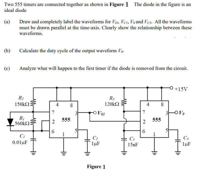
Two 555 timers are connected together as shown in Figure 1 The diode in the figure is an ideal diode (a) (b) (c) Draw an
Posted: Tue Jul 12, 2022 8:38 am
by answerhappygod
- Two 555 Timers Are Connected Together As Shown In Figure 1 The Diode In The Figure Is An Ideal Diode A B C Draw An 1 (86.67 KiB) Viewed 35 times
Two 555 timers are connected together as shown in Figure 1 The diode in the figure is an ideal diode (a) (b) (c) Draw and completely label the waveforms for Vol. Vci, Vo and VC3. All the waveforms must be drawn parallel at the time-axis. Clearly show the relationship between these waveforms. Calculate the duty cycle of the output waveform Vo. Analyze what will happen to the first timer if the diode is removed from the circuit. R₂ 150kΩ R₁ 560k2: C₁ 0.01 μF 7 2 6 8 555 R3 120kΩ -OV01 C₂ 1μF Figure 1 C3 15nF 7 2 6 4 8 555 +15V 3-0 Vo C4 1μF