Page 1 of 1
FIGURE 2 shows a fixed-bias BJT configuration to study a small signal amplifier. Assume the transistor is made of silico
Posted: Tue Jul 12, 2022 8:38 am
by answerhappygod
- Figure 2 Shows A Fixed Bias Bjt Configuration To Study A Small Signal Amplifier Assume The Transistor Is Made Of Silico 1 (141.28 KiB) Viewed 37 times
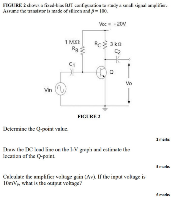
FIGURE 2 shows a fixed-bias BJT configuration to study a small signal amplifier. Assume the transistor is made of silicon and B = 100. Vcc = +20V Vin 1 ΜΩ C1 Determine the Q-point value. RB3 ww 5 RC Σ 3 ΚΩ C2 FIGURE 2 Q Vo Draw the DC load line on the I-V graph and estimate the location of the Q-point. Calculate the amplifier voltage gain (Av). If the input voltage is 10mVp, what is the output voltage? 2 marks 5 marks 6 marks