Page 1 of 1
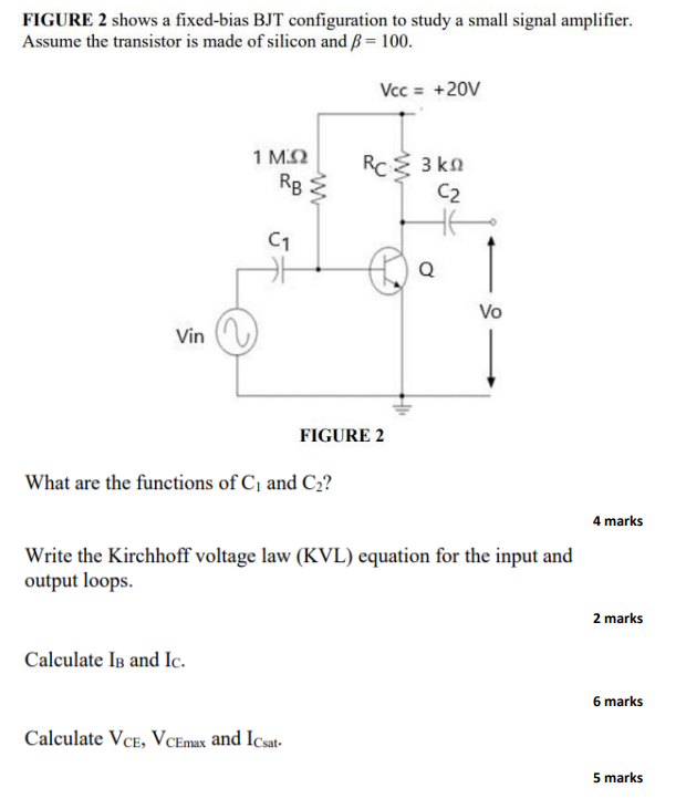
FIGURE 2 shows a fixed-bias BJT configuration to study a small signal amplifier. Assume the transistor is made of silico
Posted: Tue Jul 12, 2022 8:36 am
by answerhappygod
- Figure 2 Shows A Fixed Bias Bjt Configuration To Study A Small Signal Amplifier Assume The Transistor Is Made Of Silico 1 (133.84 KiB) Viewed 29 times
FIGURE 2 shows a fixed-bias BJT configuration to study a small signal amplifier. Assume the transistor is made of silicon and ß = 100. Vcc = +20V Vin 1 M.Q RB C1 Calculate IB and Ic. ww What are the functions of C₁ and C₂? Calculate VCE, VCEmax and Icsat. RC Σ 3 ΚΩ C2 FIGURE 2 Q Write the Kirchhoff voltage law (KVL) equation for the input and output loops. Vo 4 marks 2 marks 6 marks 5 marks