Page 1 of 1
The overhead three phase line configuration shown in Figure 1 below is for a 200 km medium length transmission line oper
Posted: Tue Jul 12, 2022 8:36 am
by answerhappygod
- The Overhead Three Phase Line Configuration Shown In Figure 1 Below Is For A 200 Km Medium Length Transmission Line Oper 1 (39.63 KiB) Viewed 50 times
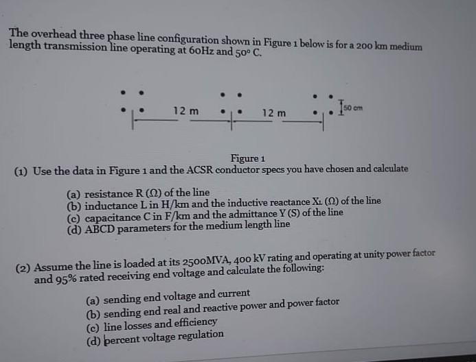
The overhead three phase line configuration shown in Figure 1 below is for a 200 km medium length transmission line operating at 60Hz and 50° C. 12 m 12 m cm Figure 1 (1) Use the data in Figure 1 and the ACSR conductor specs you have chosen and calculate (a) resistance R (22) of the line (b) inductance L in H/km and the inductive reactance Xi (0) of the line (c) capacitance C in F/km and the admittance Y (S) of the line (d) ABCD parameters for the medium length line (2) Assume the line is loaded at its 2500MVA, 400 kV rating and operating at unity power factor and 95% rated receiving end voltage and calculate the following: (a) sending end voltage and current (b) sending end real and reactive power and power factor (c) line losses and efficiency (d) percent voltage regulation