Page 1 of 1
Q2 The circuit in Figure Q2 is an active filter. (a) (b) (c) (d) Derive the expression for the voltage transfer function
Posted: Tue Jul 12, 2022 8:35 am
by answerhappygod
- Q2 The Circuit In Figure Q2 Is An Active Filter A B C D Derive The Expression For The Voltage Transfer Function 1 (49.84 KiB) Viewed 31 times
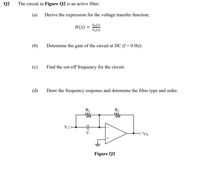
Q2 The circuit in Figure Q2 is an active filter. (a) (b) (c) (d) Derive the expression for the voltage transfer function; Vo(s) H(s) Vi(s) Determine the gain of the circuit at DC (f = 0 Hz). Find the cut-off frequency for the circuit. Draw the frequency response and determine the filter type and order. Vio- R₁ W с ਸ Figure Q2 R₂ W -O Vo