Page 1 of 1
(a) (b) Liquid A Inlet Tank (ii) Liquid B Inlet Figure O2(a) Figure Q2(a) shows an automatic liquid heating and stirring
Posted: Tue Jul 12, 2022 8:34 am
by answerhappygod
- A B Liquid A Inlet Tank Ii Liquid B Inlet Figure O2 A Figure Q2 A Shows An Automatic Liquid Heating And Stirring 1 (237.95 KiB) Viewed 31 times
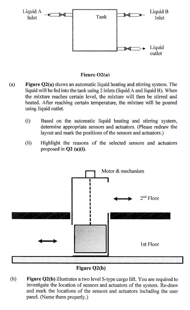
(a) (b) Liquid A Inlet Tank (ii) Liquid B Inlet Figure O2(a) Figure Q2(a) shows an automatic liquid heating and stirring system. The liquid will be fed into the tank using 2 inlets (liquid A and liquid B). When the mixture reaches certain level, the mixture will then be stirred and heated. After reaching certain temperature, the mixture will be poured using liquid outlet. (i) Liquid outlet Based on the automatic liquid heating and stirring system, determine appropriate sensors and actuators. (Please redraw the layout and mark the positions of the sensors and actuators.) Motor & mechanism Highlight the reasons of the selected sensors and actuators proposed in Q2 (a)(i). 2nd Floor 1st Floor Figure Q2(b) Figure Q2(b) illustrates a two level S-type cargo lift. You are required to investigate the location of sensors and actuators of the system. Re-draw and mark the locations of the sensors and actuators including the user panel. (Name them properly.)