Page 1 of 1
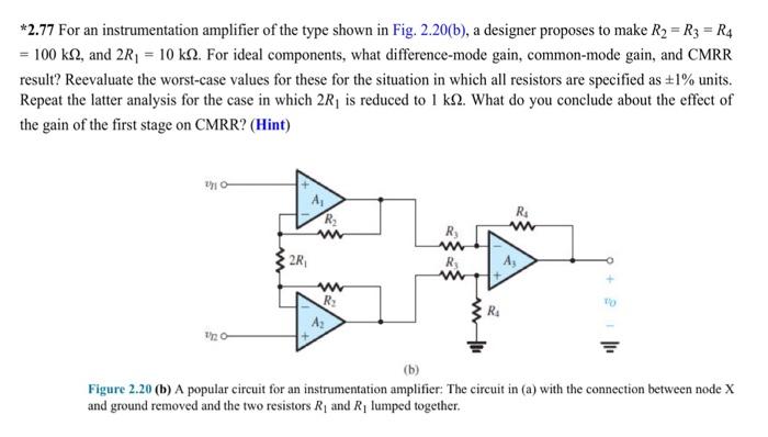
*2.77 For an instrumentation amplifier of the type shown in Fig. 2.20(b), a designer proposes to make R₂ R3 = R4 = 100 k
Posted: Tue Jul 12, 2022 8:28 am
by answerhappygod
- 2 77 For An Instrumentation Amplifier Of The Type Shown In Fig 2 20 B A Designer Proposes To Make R R3 R4 100 K 1 (33.43 KiB) Viewed 52 times
*2.77 For an instrumentation amplifier of the type shown in Fig. 2.20(b), a designer proposes to make R₂ R3 = R4 = 100 ks2, and 2R₁ = 10 k. For ideal components, what difference-mode gain, common-mode gain, and CMRR result? Reevaluate the worst-case values for these for the situation in which all resistors are specified as ±1% units. Repeat the latter analysis for the case in which 2R₁ is reduced to 1 k2. What do you conclude about the effect of the gain of the first stage on CMRR? (Hint) 2/10- 1/2 2R₁ A₁ R₂ www www R₂ R₂ www R₂ ww R₁ R₁ www (b) Figure 2.20 (b) A popular circuit for an instrumentation amplifier: The circuit in (a) with the connection between node X and ground removed and the two resistors R₁ and R₁ lumped together.