Page 1 of 1
3. The system illustrated in single line format below consist of a 25,000 kVA, 13.8 kV generator powering a motor bus th
Posted: Tue Jul 12, 2022 8:28 am
by answerhappygod
- 3 The System Illustrated In Single Line Format Below Consist Of A 25 000 Kva 13 8 Kv Generator Powering A Motor Bus Th 1 (59.15 KiB) Viewed 32 times
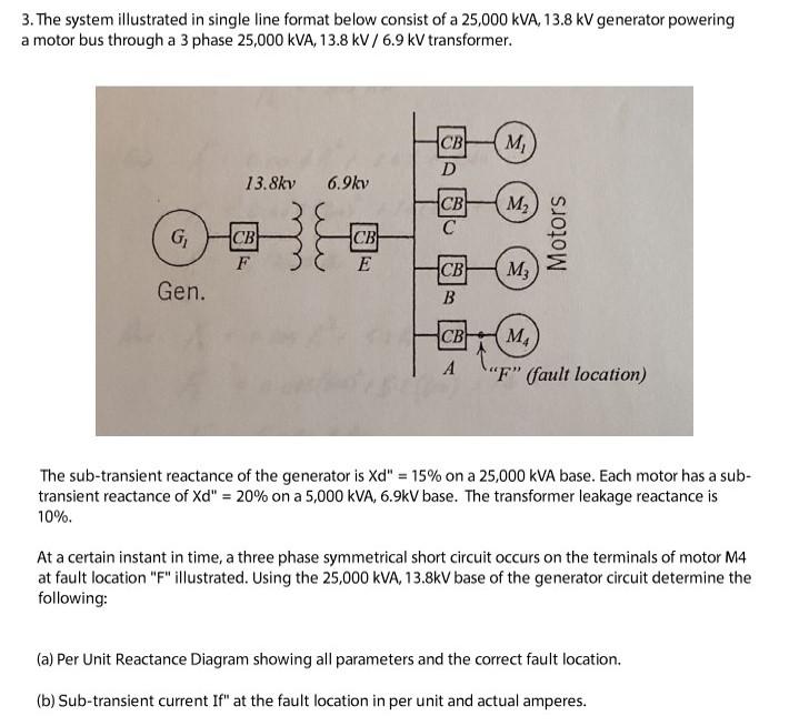
3. The system illustrated in single line format below consist of a 25,000 kVA, 13.8 kV generator powering a motor bus through a 3 phase 25,000 kVA, 13.8 kV/ 6.9 kV transformer. G₁ Gen. 13.8kv CB F 6.9kv CB E CB D CB C M₁ M₂ CB M3 B Motors CB MA AF" (fault location) The sub-transient reactance of the generator is Xd" = 15% on a 25,000 KVA base. Each motor has a sub- transient reactance of Xd" = 20% on a 5,000 kVA, 6.9kV base. The transformer leakage reactance is 10%. At a certain instant in time, a three phase symmetrical short circuit occurs on the terminals of motor M4 at fault location "F" illustrated. Using the 25,000 kVA, 13.8kV base of the generator circuit determine the following: (a) Per Unit Reactance Diagram showing all parameters and the correct fault location. (b) Sub-transient current If" at the fault location in per unit and actual amperes.