Page 1 of 1
Q1 Figure Q1(a) shows the first floor structural layout plan for a factory-office building and Figure Q1(b) shows the de
Posted: Mon Jul 11, 2022 2:43 pm
by answerhappygod
- Q1 Figure Q1 A Shows The First Floor Structural Layout Plan For A Factory Office Building And Figure Q1 B Shows The De 1 (45.93 KiB) Viewed 51 times
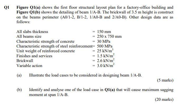
Q1 Figure Q1(a) shows the first floor structural layout plan for a factory-office building and Figure Q1(b) shows the detailing of beam 1/A-B. The brickwall of 3.5 m height is construct on the beams perimeter (A0/1-2, B/1-2, 1/A0-B and 2/A0-B). Other design data are as follows: 150 mm All slabs thickness All beams size = 250 x 750 mm = 30 MPa Characteristic strength of concrete Characteristic strength of steel reinforcement= 500 MPa Unit weight of reinforced concrete = 25 kN/m³ Finishes and services Brickwall Variable action (a) Illustrate the load cases to be considered in designing beam 1/A-B. = 1.5 kN/m² = 2.6 kN/m² = 3.0 kN/m² (b) (5 marks) Identify and analyse one of the load case in Q1(a) that will cause maximum sagging moment at span 1/A-B. (20 marks)
2 1 6m AO 2m A 4m A1 FIGURE Q1(a) 4 m Notes: 1. All First Floor Beams To Be 250 mm x 750 mm 2. All First Floor Slabs To Be 150 mm Thick B
АО 50 mm 2m H10-250 c/c H10-250- 2H25 2H25 250 mm 2H25 3H25 A Section 1-1 Ignore for calculation 700 mm 750 mm F 11- 8 m H10-250 c/c 50 mm -3H25 H10-250- Detailing of Beam 1/A-B FIGURE Q1(b) 2H25 250 mm 2H25 2H25 Section 2-2 2H25 700 mm ||~ Ignore for calculation 750 mm B