Page 1 of 1
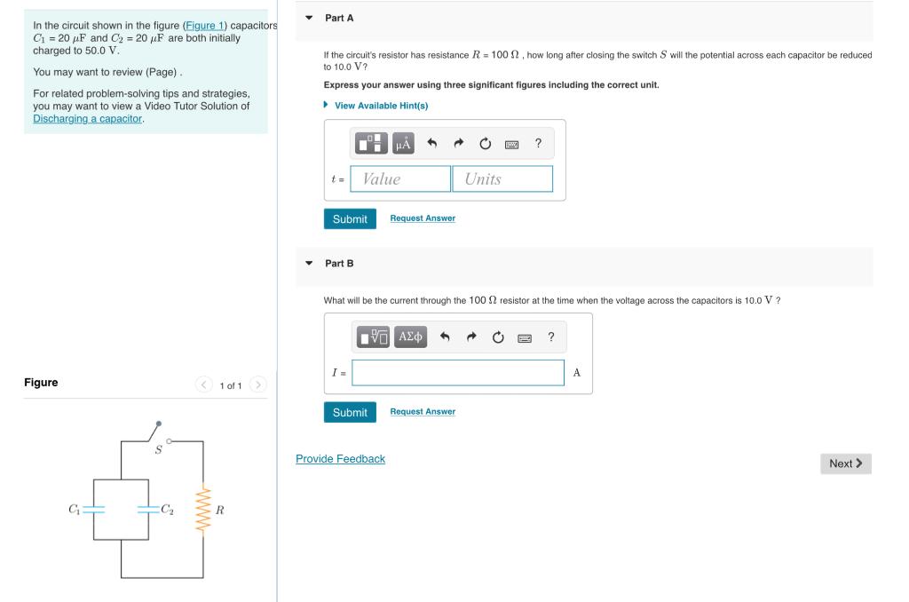
In the circuit shown in the figure (Figure 1) capacitors C₁= 20 µF and C₂ = 20 µF are both initially charged to 50.0 V.
Posted: Sun Jul 10, 2022 11:54 am
by answerhappygod
- In The Circuit Shown In The Figure Figure 1 Capacitors C 20 Uf And C 20 Uf Are Both Initially Charged To 50 0 V 1 (48.19 KiB) Viewed 48 times
In the circuit shown in the figure (Figure 1) capacitors C₁= 20 µF and C₂ = 20 µF are both initially charged to 50.0 V. You may want to review (Page). For related problem-solving tips and strategies, you may want to view a Video Tutor Solution of Discharging a capacitor. Figure G S C₂ < 1 of 1 > R ▼ ▼ Part A If the circuit's resistor has resistance R = 100 , how long after closing the switch S will the potential across each capacitor be reduced to 10.0 V? Express your answer using three significant figures including the correct unit. View Available Hint(s) t= Submit Request Answer Part B Value I= What will be the current through the 100 S2 resistor at the time when the voltage across the capacitors is 10.0 V? IVE ΑΣΦ Submit Provide Feedback 1 Units Request Answer ? B ? A Next >