Page 1 of 1
1) The following figure shows a common-emitter amplifier with voltage-divider bias. i) ii) iii) iv) input H 10 uF Vcc=20
Posted: Sat Jul 09, 2022 11:59 am
by answerhappygod
- 1 The Following Figure Shows A Common Emitter Amplifier With Voltage Divider Bias I Ii Iii Iv Input H 10 Uf Vcc 20 1 (44.6 KiB) Viewed 38 times
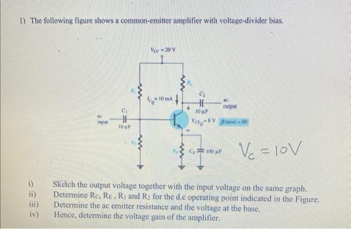
1) The following figure shows a common-emitter amplifier with voltage-divider bias. i) ii) iii) iv) input H 10 uF Vcc=20 V co 10 mA M + H 10 pF VCE &V output B(min) = 80 C100 pF V₂ = 10V Sketch the output voltage together with the input voltage on the same graph. Determine Rc, RE, R₁ and R₂ for the d.c operating point indicated in the Figure. Determine the ac emitter resistance and the voltage at the base. Hence, determine the voltage gain of the amplifier.