Page 1 of 1
Scores Pearson eText Study Area Document Sharing User Settings Course Tools In the circuit shown in (Figure 1), the capa
Posted: Sat Jul 09, 2022 11:55 am
by answerhappygod
- Scores Pearson Etext Study Area Document Sharing User Settings Course Tools In The Circuit Shown In Figure 1 The Capa 1 (55.78 KiB) Viewed 49 times
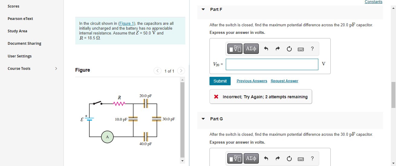
Scores Pearson eText Study Area Document Sharing User Settings Course Tools In the circuit shown in (Figure 1), the capacitors are all initially uncharged and the battery has no appreciable internal resistance. Assume that E = 50.0 V and R = 18.5. Figure A R ww 10.0 pF= 20.0 pF 40.0 pF 1 of 1 30.0 pF Part F After the switch is closed, find the maximum potential difference across the 20.0 pF capacitor. Express your answer in volts. 15. ΑΣΦ V20= Submit Previous Answers Request Answer X Incorrect; Try Again; 2 attempts remaining Part G Constants V ? After the switch is closed, find the maximum potential difference across the 30.0 pF capacitor. Express your answer in volts. 15. ΑΣΦ