Page 1 of 1
Compare the unit-step command responses of the two designs. 10.60 The system shown in Figure P10.60 represents the probl
Posted: Fri Jul 08, 2022 6:29 am
by answerhappygod
- Compare The Unit Step Command Responses Of The Two Designs 10 60 The System Shown In Figure P10 60 Represents The Probl 1 (35.62 KiB) Viewed 28 times
- Compare The Unit Step Command Responses Of The Two Designs 10 60 The System Shown In Figure P10 60 Represents The Probl 2 (28.77 KiB) Viewed 28 times
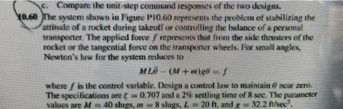
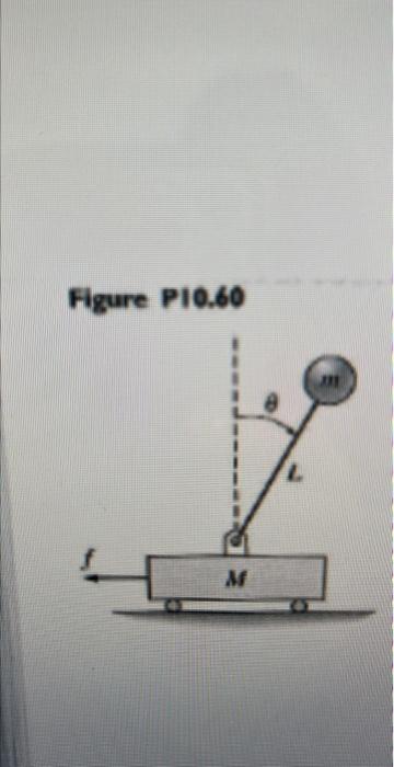
Compare the unit-step command responses of the two designs. 10.60 The system shown in Figure P10.60 represents the problem of stabilizing the attitude of a rocket during takeoff or controlling the balance of a personal transporter. The applied force/represents that from the side thrusters of the rocket or the tangential force on the transporter wheels. For small angles, Newton's law for the system reduces to ML (M+m)gö - f where is the control variable. Design a control law to maintain & near zero. The specifications are = 0.707 and a 2% settling time of 8 sec. The parameter values are M40 slugs, m8 slugs, L 20 ft, and g 32.2 ft/sec.
Figure P10.60 I M L 111