Page 1 of 1
2 Differential Amplifier Circuit Analysis The circuit in Figure 1.1(a) is called a Differential Amplifier. This circuit
Posted: Fri Jul 08, 2022 6:28 am
by answerhappygod
- 2 Differential Amplifier Circuit Analysis The Circuit In Figure 1 1 A Is Called A Differential Amplifier This Circuit 1 (120.36 KiB) Viewed 30 times
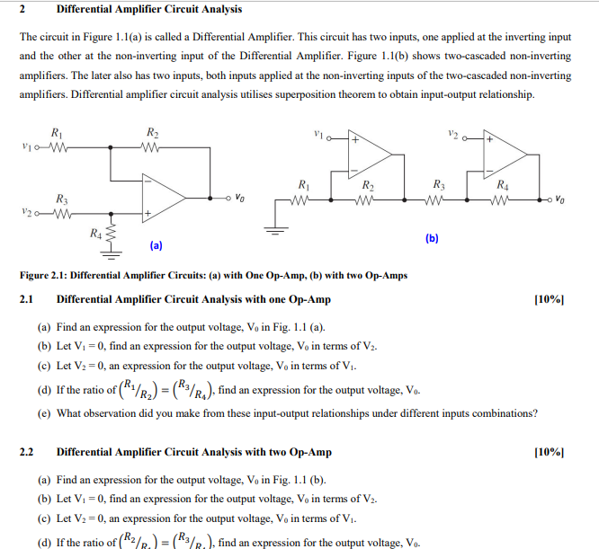
2 Differential Amplifier Circuit Analysis The circuit in Figure 1.1(a) is called a Differential Amplifier. This circuit has two inputs, one applied at the inverting input and the other at the non-inverting input of the Differential Amplifier. Figure 1.1(b) shows two-cascaded non-inverting amplifiers. The later also has two inputs, both inputs applied at the non-inverting inputs of the two-cascaded non-inverting amplifiers. Differential amplifier circuit analysis utilises superposition theorem to obtain input-output relationship. R₁ V10 M R3 1₂0 M 2.1 R₂ w # Vo (a) 2.2 R₁ R₁ ww Figure 2.1: Differential Amplifier Circuits: (a) with One Op-Amp, (b) with two Op-Amps Differential Amplifier Circuit Analysis with one Op-Amp R₂ ww R3 ww (b) Differential Amplifier Circuit Analysis with two Op-Amp (a) Find an expression for the output voltage, V₁ in Fig. 1.1 (b). (b) Let V₁ = 0, find an expression for the output voltage, Vo in terms of V₂. (c) Let V₂ = 0, an expression for the output voltage, Vo in terms of V₁. (d) If the ratio of (2/2) = (R3/R), find an expression for the output voltage, Vo. R₁ www (a) Find an expression for the output voltage, V₁ in Fig. 1.1 (a). (b) Let V₁ = 0, find an expression for the output voltage, Vo in terms of V₂. (c) Let V₂ = 0, an expression for the output voltage, Vo in terms of V₁. (d) If the ratio of (¹/₂) = R3/R), find an expression for the output voltage, Vo. (e) What observation did you make from these input-output relationships under different inputs combinations? to vo [10%] [10%]