Page 1 of 1
Part 1: Non-Inverting Op Amp Build this circuit on your breadboard Let R₁ = 3k2 and R₂-10k2 • Let V₁ be the Function Gen
Posted: Fri Jul 08, 2022 6:25 am
by answerhappygod
- Part 1 Non Inverting Op Amp Build This Circuit On Your Breadboard Let R 3k2 And R 10k2 Let V Be The Function Gen 1 (78.06 KiB) Viewed 32 times
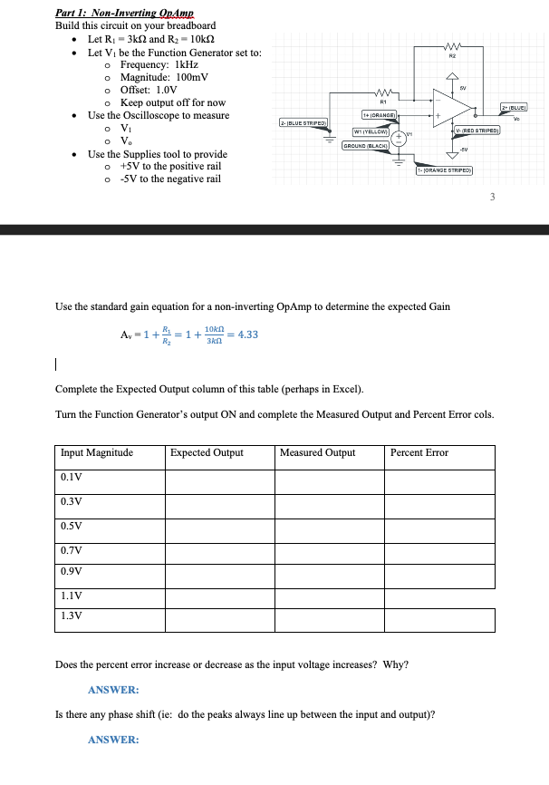
Part 1: Non-Inverting Op Amp Build this circuit on your breadboard Let R₁ = 3k2 and R₂-10k2 • Let V₁ be the Function Generator set to: o Frequency: 1kHz o Magnitude: 100mV o Offset: 1.0V o Keep output off for now • Use the Oscilloscope to measure • Use the Supplies tool to provide o +5V to the positive rail o -5V to the negative rail o V₁ o V. 0.3V Input Magnitude 0.1V 0.5V 0.7V 0,9V Av=1+₁=1+3 = 4.33 R₂ 1.1V 1.3V 2-BLUE STRIPED Use the standard gain equation for a non-inverting OpAmp to determine the expected Gain 10kn 3kn Expected Output www R1 1+ (ORANGE) W(YELLOW) GROUND (BLACK) + Measured Output R2 1 Complete the Expected Output column of this table (perhaps in Excel). Turn the Function Generator's output ON and complete the Measured Output and Percent Error cols. SV 1-JORANGE STRIPED) Percent Error Does the percent error increase or decrease as the input voltage increases? Why? ANSWER: Is there any phase shift (ie: do the peaks always line up between the input and output)? ANSWER: V-(RED STRIPED) -SV 3 2+(BLUE)