Page 1 of 1
Learning Goal: To analyze op-amp circuits that invert the voltage applied to the negative op-amp terminal. Before procee
Posted: Fri Jul 08, 2022 6:23 am
by answerhappygod
- Learning Goal To Analyze Op Amp Circuits That Invert The Voltage Applied To The Negative Op Amp Terminal Before Procee 1 (84.52 KiB) Viewed 39 times
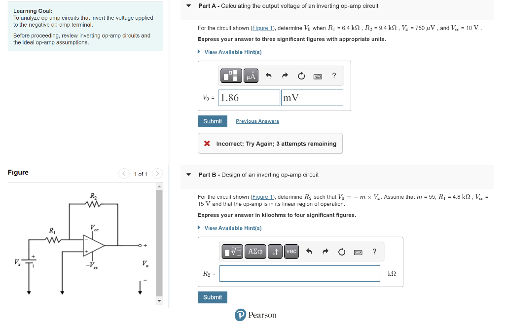
Learning Goal: To analyze op-amp circuits that invert the voltage applied to the negative op-amp terminal. Before proceeding, review inverting op-amp circuits and the ideal op-amp assumptions. Figure R₂ -Vec 1 of 1 > V₂ Part A - Calculating the output voltage of an inverting op-amp circuit For the circuit shown (Figure 1), determine Vo when R₁ = 6.4 kN, R₂ = 9.4 kN, V₂ = 750 μV, and Vcc= 10 V. Express your answer to three significant figures with appropriate units. ► View Available Hint(s) Vo = 1.86 Submit Previous Answers X Incorrect; Try Again; 3 attempts remaining Part B - Design of an inverting op-amp circuit R₂ = mV Submit For the circuit shown (Figure 1), determine R₂ such that V = 15 V and that the op-amp is in its linear region of operation. Express your answer in kiloohms to four significant figures. ► View Available Hint(s ? AΣo↓ vec P Pearson m x V₂. Assume that m = 55, R₁ = 4.8 k, V= ? ΚΩ