Page 1 of 1
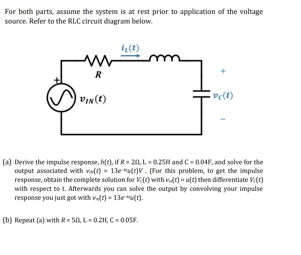
For both parts, assume the system is at rest prior to application of the voltage source. Refer to the RLC circuit diagra
Posted: Fri Jul 08, 2022 6:22 am
by answerhappygod
- For Both Parts Assume The System Is At Rest Prior To Application Of The Voltage Source Refer To The Rlc Circuit Diagra 1 (160.51 KiB) Viewed 44 times
For both parts, assume the system is at rest prior to application of the voltage source. Refer to the RLC circuit diagram below. W R VIN(t) il(t) + (b) Repeat (a) with R= 50, L = 0.2H, C = 0.05F. .vc(t) (a) Derive the impulse response, h(t), if R = 20, L = 0.25H and C = 0.04F, and solve for the output associated with VIN(t) = 13e-4tu(t)V. (For this problem, to get the impulse response, obtain the complete solution for Vc(t) with Vin(t) = u(t) then differentiate Vc(t) with respect to t. Afterwards you can solve the output by convolving your impulse response you just got with Vin(t) = 13e-4tu(t).