Page 1 of 1
Program 5 [10 points] 8 DIP switches are connected to Port A pins (PA7-PA0). The settings on these 8 DIP switches repres
Posted: Fri Jul 08, 2022 6:21 am
by answerhappygod
- Program 5 10 Points 8 Dip Switches Are Connected To Port A Pins Pa7 Pa0 The Settings On These 8 Dip Switches Repres 1 (74.83 KiB) Viewed 42 times
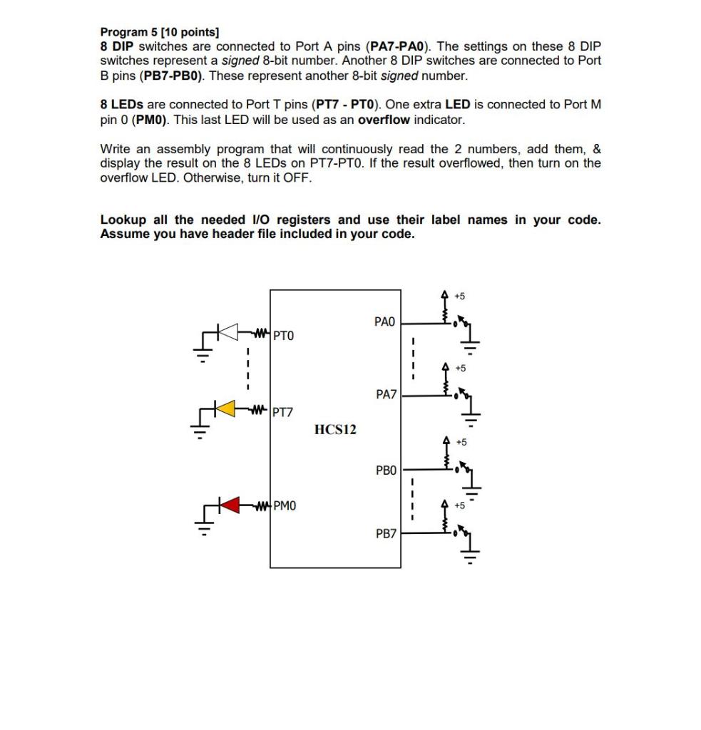
Program 5 [10 points] 8 DIP switches are connected to Port A pins (PA7-PA0). The settings on these 8 DIP switches represent a signed 8-bit number. Another 8 DIP switches are connected to Port B pins (PB7-PB0). These represent another 8-bit signed number. 8 LEDs are connected to Port T pins (PT7 - PT0). One extra LED is connected to Port M pin 0 (PMO). This last LED will be used as an overflow indicator. Write an assembly program that will continuously read the 2 numbers, add them, & display the result on the 8 LEDs on PT7-PTO. If the result overflowed, then turn on the overflow LED. Otherwise, turn it OFF. Lookup all the needed I/O registers and use their label names in your code. Assume you have header file included in your code. 4₁. WYPTO WPT7
WWW.PMO HCS12 PAO PA7 РВО PB7 Hl. Hl.
Your Code goes here INCLUDE 'mc9s12dg256.inc' Entry: ORG $4000 ; Interrupt Vectors ORG $FFFE DC.W Entry