Page 1 of 1
QUESTION 3 (C01,PO2,C4) Figure shows the diagram of transmission system. n. The ratings and reactance of the various com
Posted: Fri Jul 08, 2022 6:19 am
by answerhappygod
- Question 3 C01 Po2 C4 Figure Shows The Diagram Of Transmission System N The Ratings And Reactance Of The Various Com 1 (39.86 KiB) Viewed 45 times
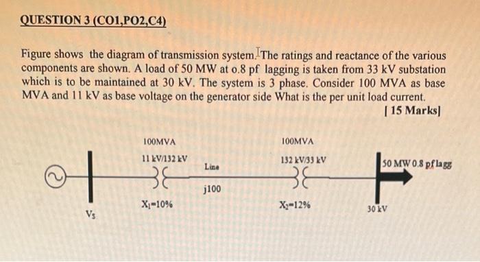
QUESTION 3 (C01,PO2,C4) Figure shows the diagram of transmission system. n. The ratings and reactance of the various components are shown. A load of 50 MW at o.8 pf lagging is taken from 33 kV substation which is to be maintained at 30 kV. The system is 3 phase. Consider 100 MVA as base MVA and 11 kV as base voltage on the generator side What is the per unit load current. [ 15 Marks] 100MVA 11 kV/132 kV of 38 X₁-10% Vs Line j100 100MVA 132 kV/33 kV 38 X₂-12% 50 MW 0.8 pflagg 30 kV