- 1 (151.6 KiB) Viewed 55 times
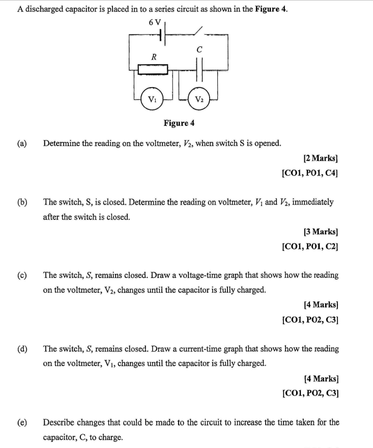
A discharged capacitor is placed in to a series circuit as shown in the Figure 4. 6V (a) (c) (d) V₁ (e) ر C V₂ (b) The switch, S, is closed. Determine the reading on voltmeter, V₁ and V2, immediately after the switch is closed. Figure 4 Determine the reading on the voltmeter, V2, when switch S is opened. [2 marks] [C01, P01, C4] [3 Marks] [CO1, P01, C2] The switch, S, remains closed. Draw a voltage-time graph that shows how the reading on the voltmeter, V2, changes until the capacitor is fully charged. [4 Marks] [C01, PO2, C3] The switch, S, remains closed. Draw a current-time graph that shows how the reading on the voltmeter, V₁, changes until the capacitor is fully charged. [4 Marks] [CO1, PO2, C3] Describe changes that could be made to the circuit to increase the time taken for the capacitor, C, to charge.