Page 1 of 1
As illustrated in Figure 1, the rectangular bar with dimensions of 250 mm by 400 mm is subjected to three loads of 15 kN
Posted: Fri Jul 08, 2022 5:53 am
by answerhappygod
- As Illustrated In Figure 1 The Rectangular Bar With Dimensions Of 250 Mm By 400 Mm Is Subjected To Three Loads Of 15 Kn 1 (38.34 KiB) Viewed 40 times
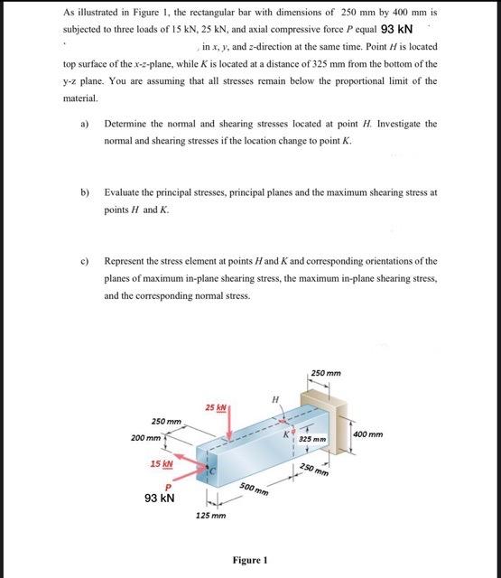
As illustrated in Figure 1, the rectangular bar with dimensions of 250 mm by 400 mm is subjected to three loads of 15 kN, 25 kN, and axial compressive force P equal 93 kN in x, y, and z-direction at the same time. Point / is located top surface of the x-z-plane, while K is located at a distance of 325 mm from the bottom of the y-z plane. You are assuming that all stresses remain below the proportional limit of the material. a) Determine the normal and shearing stresses located at point H. Investigate the normal and shearing stresses if the location change to point K. b) Evaluate the principal stresses, principal planes and the maximum shearing stress at points H and K. c) Represent the stress element at points H and K and corresponding orientations of the planes of maximum in-plane shearing stress, the maximum in-plane shearing stress, and the corresponding normal stress. 250 mm 200 mm 15 kN 93 kN 25 kN 125 mm 500 mm Figure 1 250 mm 325 mm 250 mm 400 mm