Page 1 of 1
Figure 5.1 12.0 V 2.56 μF 7.22 μF 12 μF HH 4.25 μF 8.35 μF b. The circuit in Figure 5.1 depicts five capacitors arranged
Posted: Thu Jul 07, 2022 2:02 pm
by answerhappygod
- 1 (62.1 KiB) Viewed 46 times
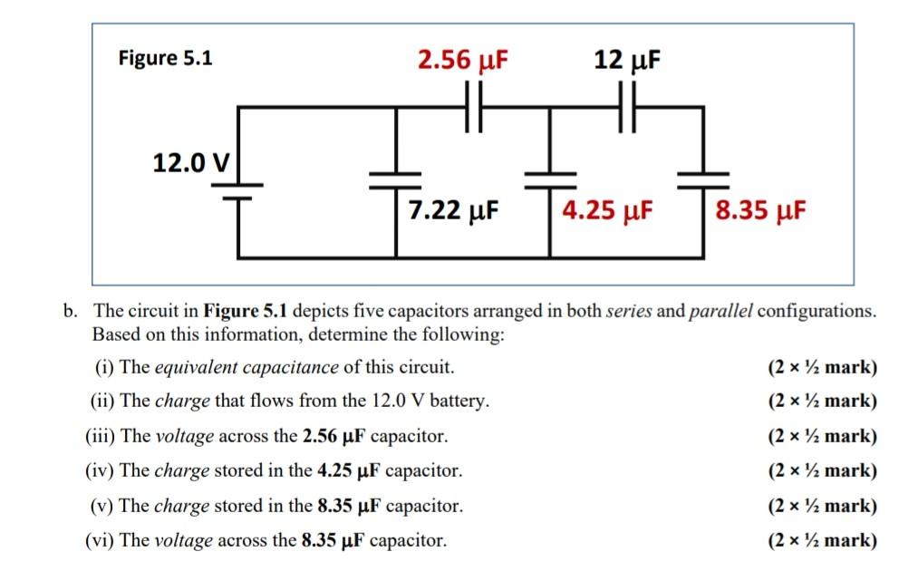
Figure 5.1 12.0 V 2.56 μF 7.22 μF 12 μF HH 4.25 μF 8.35 μF b. The circuit in Figure 5.1 depicts five capacitors arranged in both series and parallel configurations. Based on this information, determine the following: (i) The equivalent capacitance of this circuit. (ii) The charge that flows from the 12.0 V battery. (iii) The voltage across the 2.56 µF capacitor. (iv) The charge stored in the 4.25 µF capacitor. (v) The charge stored in the 8.35 µF capacitor. (vi) The voltage across the 8.35 µF capacitor. (2 x ½ mark) (2 x ½ mark) (2 x ¹ mark) (2 x ½ mark) (2 x ¹ mark) (2 x ½ mark)