Page 1 of 1
The diagram below depicts an RC-circuit where C = 6.25 MF, R1 - 12.0, R2 = 26.02, and V0 = 2.00 Volts. Capacitor initial
Posted: Sun Apr 17, 2022 3:54 pm
by answerhappygod
- The Diagram Below Depicts An Rc Circuit Where C 6 25 Mf R1 12 0 R2 26 02 And V0 2 00 Volts Capacitor Initial 1 (192.7 KiB) Viewed 34 times
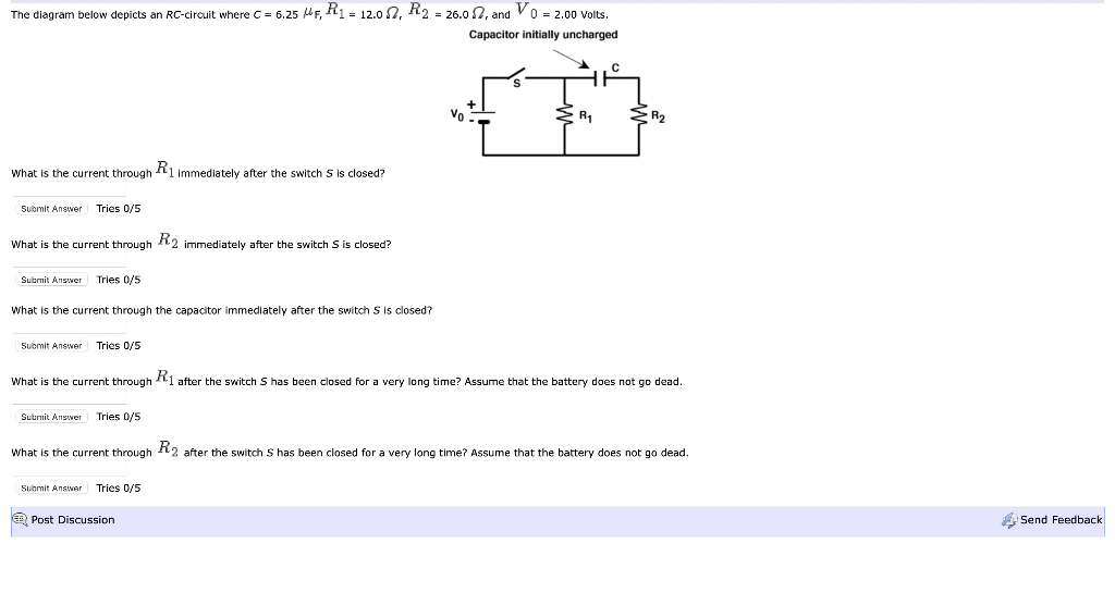
The diagram below depicts an RC-circuit where C = 6.25 MF, R1 - 12.0, R2 = 26.02, and V0 = 2.00 Volts. Capacitor initially uncharged R1 What is the current through R1 immediately after the switch S is closed? Submit Answer Tries 0/5 What is the current through R2 immediately after the switch S is closed? Submit Answer Tries 0/5 What is the current through the capacitor immediately after the switch S is closed? Submit Answer Tries 0/5 What is the current through R1 after the switch S has been closed for a very long time? Assume that the battery does not go dead. Submit Answer Tries 0/5 What is the current through R2 after the switch S has been closed for a very long time? Assume that the battery does not go dead. Submit Answer Tries 0/5 e Post Discussion Send Feedback