Page 1 of 1
Question 3 For the linear potentiometer shown in the figure below. and given Vout 100 V when the wiper is at maximum tra
Posted: Tue Apr 12, 2022 10:17 am
by answerhappygod
- Question 3 For The Linear Potentiometer Shown In The Figure Below And Given Vout 100 V When The Wiper Is At Maximum Tra 1 (126.12 KiB) Viewed 39 times
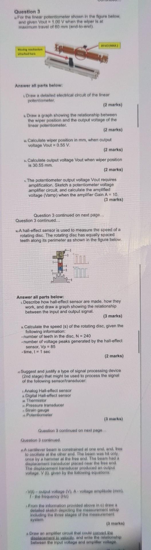
Question 3 For the linear potentiometer shown in the figure below. and given Vout 100 V when the wiper is at maximum travel of 60 mm (end-to-end), OMARI Answer all parts below: Draw a detailed electrical circuit of the linear potentiometer (2 marks) *Draw a graph showing the relationship between the wiper position and the output voltage of the linear potentiometer. (2 marks) w Calculate wiper position in mm, when output voltage Vout = 0.55 V. (2 marks) Calculate output voltage Vout when wiper position is 30.55 mm (2 marks) The potentiometer output voltage Vout requires amplification. Sketch a potentiometer voltage amplifier circuit, and calculate the amplified voltage (Vamp) when the amplifier Gain A = 10. (3 marks) Question 3 continued on next page... Question 3 continued.. SA hall-effect sensor is used to measure the speed of a rotating disc. The rotating disc has equally spaced teeth along its perimeter as shown in the figure below. M Answer all parts below: Describe how hall-effect sensor are made, how they work, and draw a graph showing the relationship between the input and output signal. (3 marks) Calculate the speed (s) of the rotating disc, given the following information: -number of teeth in the disc, N = 240 number of voltage peaks generated by the hall-effect sensor, Vp = 85 time, t 1 sec (2 marks) . Suggest and justify a type of signal processing device (2nd stage) that might be used to process the signal of the following sensor/transducer Analog Hall-effect sensor Digital Hall-effect sensor Thermistor Pressure transducer Strain gaugo Potentiometer (3 marks) Question 3 continued on next page... Question 3 continued Acantilever beam is constrained at one end, and, tre lo oscillato al the other ond. The beam was hit only once by a hammor at the free end. The beam had a displacement transducer placed near the free end The displacement transducer produced an outpsa vollago. V. given by the following equations (0 - output voltage (V). A voltage amplitude (mm) the frequency (H) From the information provided above in o) drowa detailed skolch dopicing the measurement solup including the three stages of the measurement syslom (3 marks) Drow an amplifier circuit that could convert the displacement lo velocily, and write the relationship between the input voltage and amplifier voltage