Page 1 of 1
Using Figure 4.1 with Zline = (5+j8), calculate the active and reactive power received and transferred within the interc
Posted: Tue Apr 12, 2022 10:17 am
by answerhappygod
- Using Figure 4 1 With Zline 5 J8 Calculate The Active And Reactive Power Received And Transferred Within The Interc 1 (77.08 KiB) Viewed 47 times
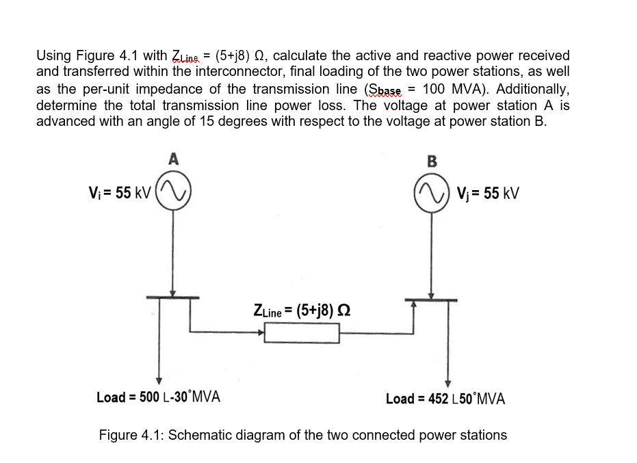
Using Figure 4.1 with Zline = (5+j8), calculate the active and reactive power received and transferred within the interconnector, final loading of the two power stations, as well as the per-unit impedance of the transmission line (Sbase = 100 MVA). Additionally, determine the total transmission line power loss. The voltage at power station A is advanced with an angle of 15 degrees with respect to the voltage at power station B. A B Vi= 55 kV = Vj = 55 kV ZLine = (5+j8) 12 Load = 500 L-30°MVA Load = 452 L50°MVA = L Figure 4.1: Schematic diagram of the two connected power stations