Page 1 of 1
1. Connect and construct the LM741 op-amp circuit as shown in Figure 1. The pin numbers for the OPAMP can be refered as
Posted: Tue Apr 12, 2022 10:16 am
by answerhappygod
- 1 Connect And Construct The Lm741 Op Amp Circuit As Shown In Figure 1 The Pin Numbers For The Opamp Can Be Refered As 1 (33.9 KiB) Viewed 36 times
- 1 Connect And Construct The Lm741 Op Amp Circuit As Shown In Figure 1 The Pin Numbers For The Opamp Can Be Refered As 2 (18.46 KiB) Viewed 36 times
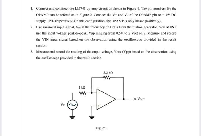
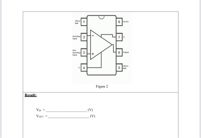
1. Connect and construct the LM741 op-amp circuit as shown in Figure 1. The pin numbers for the OPAMP can be refered as in Figure 2. Connect the V+ and V- of the OPAMP pin to +10V DC supply GND respectively. (In this configuration, the OPAMP is only biased positively). 2. Use sinusodal input signal, Vin at the frequency of 1 kHz from the funtion generator. You MUST use the input voltage peak-to-peak, Vpp ranging from 0.5V to 2 Volt only. Measure and record the VIN input signal based on the observation using the oscilloscope provided in the result section. 3. Measure and record the reading of the ouput voltage, Vout (Vpp) based on the observation using the oscilloscope provided in the result section. 2.2 ΚΩ w 1 ΚΩ w Vour VIN Figure 1
Of 8 be pl the 3 6 Figure 2 Result: VIN VOLT (V) (V)