Page 1 of 1
(c) Figure 2 shows the schematic diagram of an electromechanical system. Determine (s) the transfer function. of the sys
Posted: Tue Apr 12, 2022 10:13 am
by answerhappygod
- C Figure 2 Shows The Schematic Diagram Of An Electromechanical System Determine S The Transfer Function Of The Sys 1 (27.69 KiB) Viewed 29 times
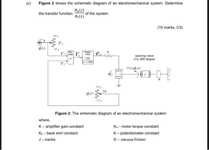
(c) Figure 2 shows the schematic diagram of an electromechanical system. Determine (s) the transfer function. of the system. Bi(s) (10 marks, C3) ..) es Power V Amp 100 +100) opening valve 0 to 360 degree V. TC) 0,6) ADE VB 0,0) Figure 2: The schematic diagram of an electromechanical system where K-amplifier gain constant Km- motor torque constant Ko-back emf constant K-potentiometer constant J - inertia D-viscous friction