Page 1 of 1
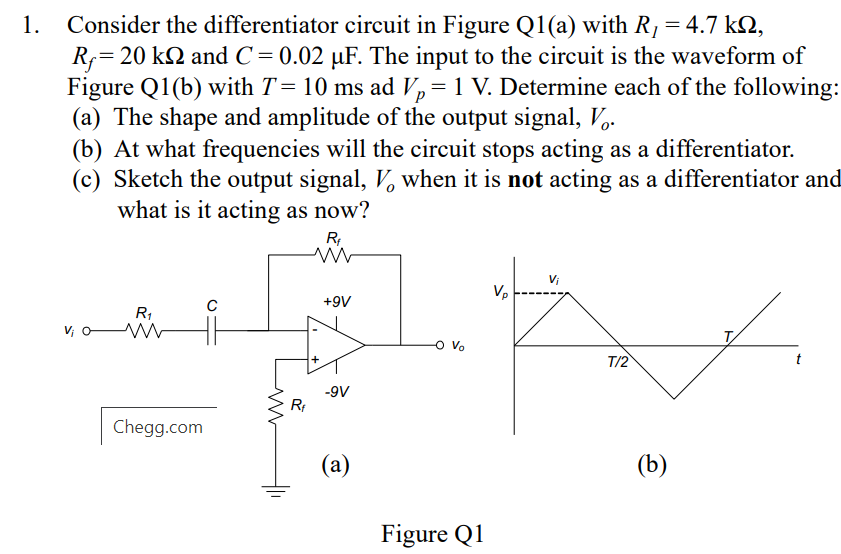
= р 1. Consider the differentiator circuit in Figure Q1(a) with R, = 4.7 k2, R;= 20 k 2 and C = 0.02 uF. The input to th
Posted: Tue Apr 12, 2022 10:13 am
by answerhappygod
- 1 (100.27 KiB) Viewed 50 times
= р 1. Consider the differentiator circuit in Figure Q1(a) with R, = 4.7 k2, R;= 20 k 2 and C = 0.02 uF. The input to the circuit is the waveform of Figure Q1(b) with T= 10 ms ad Vo=1 V. Determine each of the following: (a) The shape and amplitude of the output signal, Vo. (b) At what frequencies will the circuit stops acting as a differentiator. (c) Sketch the output signal, V, when it is not acting as a differentiator and what is it acting as now? RA Vi с +9V R1 V0VW Т. Vo T/2 t -9V RI answers.com (a) (b) HH Figure Q1