Page 1 of 1
2. For the 2nd order low-pass filter circuit shown in figure: a) Please derive the expression of its transfer function H
Posted: Tue Apr 12, 2022 10:08 am
by answerhappygod
- 2 For The 2nd Order Low Pass Filter Circuit Shown In Figure A Please Derive The Expression Of Its Transfer Function H 1 (46.67 KiB) Viewed 31 times
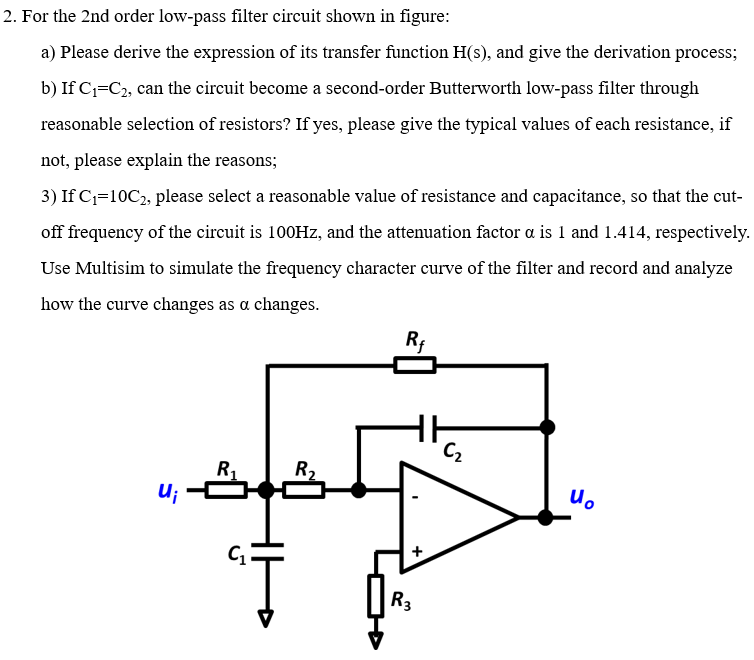
2. For the 2nd order low-pass filter circuit shown in figure: a) Please derive the expression of its transfer function H(s), and give the derivation process; b) If C1=C2, can the circuit become a second-order Butterworth low-pass filter through reasonable selection of resistors? If yes, please give the typical values of each resistance, if not, please explain the reasons; 3) If C=10C2, please select a reasonable value of resistance and capacitance, so that the cut- off frequency of the circuit is 100Hz, and the attenuation factor a is 1 and 1.414, respectively. Use Multisim to simulate the frequency character curve of the filter and record and analyze how the curve changes as a changes. RA C2 R1 R U; uo с. "] R3