Page 1 of 1
← ? Lab Manuals PHY108L-9 29°C Cloudy X C answers Search ☐ classroom.google.com/c/NDk2MTc2MjU4OTA2/m/NDk2NDgzNzA2Njlz/deta
Posted: Wed Jul 06, 2022 11:28 am
by answerhappygod
- Lab Manuals Phy108l 9 29 C Cloudy X C Chegg Search Classroom Google Com C Ndk2mtc2mju4ota2 M Ndk2ndgznza2njlz Deta 1 (91.63 KiB) Viewed 12 times
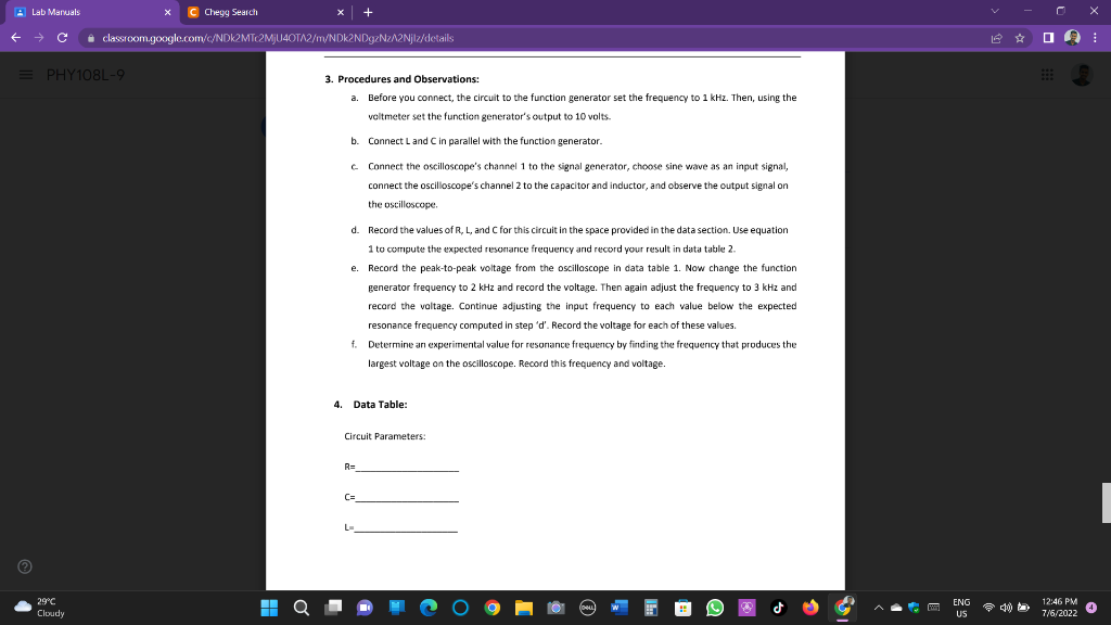
← ? Lab Manuals PHY108L-9 29°C Cloudy X C answers Search ☐ classroom.google.com/c/NDk2MTc2MjU4OTA2/m/NDk2NDgzNzA2Njlz/details 3. Procedures and Observations: a. Before you connect, the circuit to the function generator set the frequency to 1 kHz. Then, using the voltmeter set the function generator's output to 10 volts. Connect L and C in parallel with the function generator. c. Connect the oscilloscope's channel 1 to the signal generator, choose sine wave as an input signal, connect the oscilloscope's channel 2 to the capacitor and inductor, and observe the output signal on the oscilloscope. b. + d. Record the values of R, L, and C for this circuit in the space provided in the data section. Use equation 1 to compute the expected resonance frequency and record your result in data table 2. Record the peak-to-peak voltage from the oscilloscope in data table 1. Now change the function generator frequency to 2 kHz and record the voltage. Then again adjust the frequency to 3 kHz and record the voltage. Continue adjusting the input frequency to each value below the expected resonance frequency computed in step 'd'. Record the voltage for each of these values. f. Determine an experimental value for resonance frequency by finding the frequency that produces the largest voltage on the oscilloscope. Record this frequency and voltage. e. 4. Data Table: Circuit Parameters: R= C= L ENG US ☎ 400 0 □ ::: 12:46 PM 7/6/2022 X ⠀ | O