Page 1 of 1
Question 2 Strain induced due to applied masses in an aluminium rod are investigated experimentally. The aluminium rod i
Posted: Tue Apr 12, 2022 10:00 am
by answerhappygod
- Question 2 Strain Induced Due To Applied Masses In An Aluminium Rod Are Investigated Experimentally The Aluminium Rod I 1 (122.61 KiB) Viewed 38 times
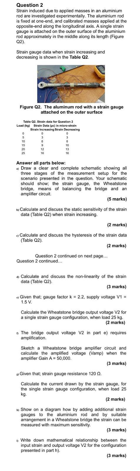
Question 2 Strain induced due to applied masses in an aluminium rod are investigated experimentally. The aluminium rod is fixed at one-end, and calibrated masses applied at the opposite-end along the longitudinal axis. A single strain gauge is attached on the outer surface of the aluminium rod approximately in the middle along its length (Figure Q2). Strain gauge data when strain increasing and decreasing is shown in the Table Q2. Figure Q2. The aluminum rod with a strain gauge attached on the outer surface Table Q2. Strain data for Question 2 Load (kg) Strain Data (pc) in micro-strain Strain Increasing Strain Decreasing 0 0 0 0 5 3 3 3 10 6 6 6 15 9 10 20 12 13 25 16 16 Answer all parts below: a) Draw a clear and complete schematic showing all three stages of the measurement setup for the scenario presented in the question. Your schematic should show; the strain gauge, the Wheatstone bridge, means of balancing the bridge and an amplifier circuit. (5 marks) b) Calculate and discuss the static sensitivity of the strain data (Table Q2) when strain increasing. (2 marks) Calculate and discuss the hysteresis of the strain data (Table Q2). . (2 marks) Question 2 continued on next page... Question 2 continued... d) Calculate and discuss the non-linearity of the strain data (Table Q2). (3 marks) . Given that: gauge factor k = 2.2, supply voltage V1 = 1.5 V. Calculate the Wheatstone bridge output voltage V2 for a single strain gauge configuration, when load 25 kg. (2 marks) The bridge output voltage V2 in part e) requires amplification. Sketch a Wheatstone bridge amplifier circuit and calculate the amplified voltage (Vamp) when the amplifier Gain A = 50,000 (3 marks) Given that; strain gauge resistance 120 2. Calculate the current drawn by the strain gauge, for the single strain gauge configuration, when load 25 kg. (2 marks) h) Show on a diagram how by adding additional strain gauges to the aluminium rod and by suitable arrangement in a Wheatstone bridge the strain can be measured with maximum sensitivity. (3 marks) Write down mathematical relationship between the input strain and output voltage V2 for the configuration presented in part h). (3 marks)