- Etiis Week 6 Lab 1 Watch The Week 6 Lab Video Series Parallel Rlc Circuits 17 17 2 From The Circuit Below Calcula 1 (125.39 KiB) Viewed 23 times
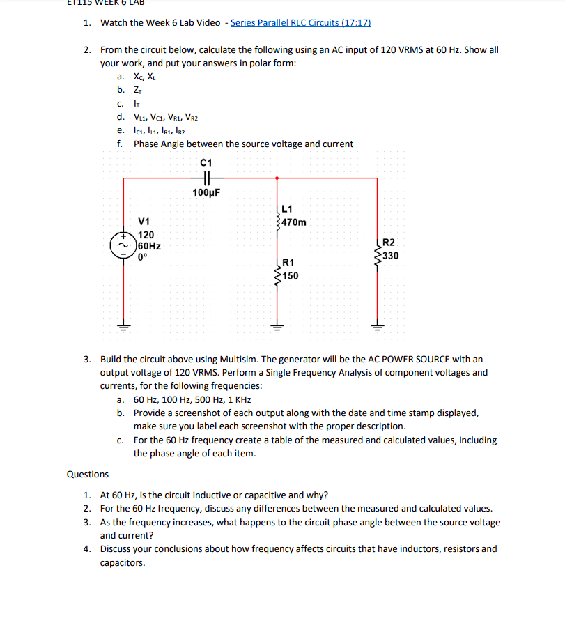
ETIIS WEEK 6 LAB 1. Watch the Week 6 Lab Video - Series Parallel RLC Circuits (17:17) 2. From the circuit below, calculate the following using an AC input of 120 VRMS at 60 Hz. Show all your work, and put your answers in polar form: a. Xc, XL b. Z₁ C. IT d. VL1, VC1, VR1, VR2 e. Ic₁, L1, R1, R2 f. Phase Angle between the source voltage and current V1 120 60Hz 0° C1 HH 100μF L1 470m R1 150 R2 330 3. Build the circuit above using Multisim. The generator will be the AC POWER SOURCE with an output voltage of 120 VRMS. Perform a Single Frequency Analysis of component voltages and currents, for the following frequencies: a. 60 Hz, 100 Hz, 500 Hz, 1 KHz b. Provide a screenshot of each output along with the date and time stamp displayed, make sure you label each screenshot with the proper description. c. For the 60 Hz frequency create a table of the measured and calculated values, including the phase angle of each item.
Questions 1. At 60 Hz, is the circuit inductive or capacitive and why? 2. For the 60 Hz frequency, discuss any differences between the measured and calculated values. 3. As the frequency increases, what happens to the circuit phase angle between the source voltage and current? 4. Discuss your conclusions about how frequency affects circuits that have inductors, resistors and capacitors.