Page 1 of 1
6. Buck Converter a) Resistive Load The archive contains 5 oscilloscope images that capture the operati
Posted: Sun Jul 03, 2022 12:14 pm
by answerhappygod
- 6 Buck Converter A Resistive Load The Archive Data Set 1 Zip Contains 5 Oscilloscope Images That Capture The Operati 1 (105.33 KiB) Viewed 18 times
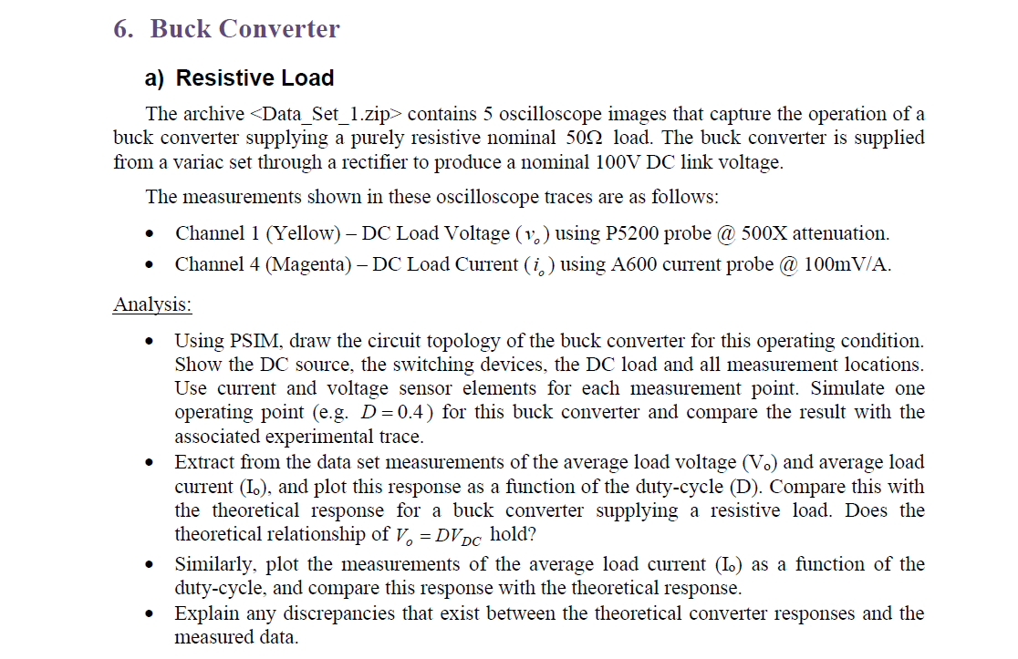
6. Buck Converter a) Resistive Load The archive <Data_Set_1.zip> contains 5 oscilloscope images that capture the operation of a buck converter supplying a purely resistive nominal 500 load. The buck converter is supplied from a variac set through a rectifier produce a nominal 100V DC link voltage. The measurements shown in these oscilloscope traces are as follows: Channel 1 (Yellow) - DC Load Voltage (v.) using P5200 probe @ 500X attenuation. Channel 4 (Magenta) – DC Load Current (i) using A600 current probe @ 100mV/A. Analysis: Using PSIM, draw the circuit topology of the buck converter for this operating condition. Show the DC source, the switching devices, the DC load and all measurement locations. Use current and voltage sensor elements for each measurement point. Simulate one operating point (e.g. D=0.4) for this buck converter and compare the result with the associated experimental trace. Extract from the data set measurements of the average load voltage (V.) and average load current (I.), and plot this response as a function of the duty-cycle (D). Compare this with the theoretical response for a buck converter supplying a resistive load. Does the theoretical relationship of V = DVDC hold? • Similarly, plot the measurements of the average load current (I.) as a function of the duty-cycle, and compare this response with the theoretical response. Explain any discrepancies that exist between the theoretical converter responses and the measured data.