Page 1 of 1
WL Shutter Door SF1 WSS Counter Top (Working Area) Base O Figure 1. Fume hood suction controller. Mr. Chua is trying to
Posted: Sun Jul 03, 2022 12:14 pm
by answerhappygod
- Wl Shutter Door Sf1 Wss Counter Top Working Area Base O Figure 1 Fume Hood Suction Controller Mr Chua Is Trying To 1 (349.02 KiB) Viewed 21 times
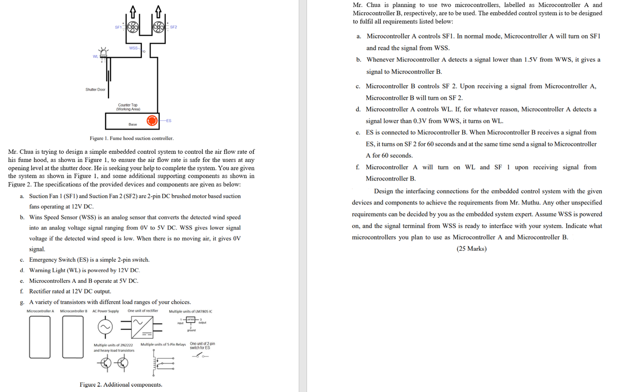
WL Shutter Door SF1 WSS Counter Top (Working Area) Base O Figure 1. Fume hood suction controller. Mr. Chua is trying to design a simple embedded control system to control the air flow rate of his fume hood, as shown in Figure 1, to ensure the air flow rate is safe for the users at any opening level at the shutter door. He is seeking your help to complete the system. You are given the system as shown in Figure 1, and some additional supporting components as shown in Figure 2. The specifications of the provided devices and components are given as below: c. Emergency Switch (ES) is a simple 2-pin switch. d. Warning Light (WL) is powered by 12V DC. e. Microcontrollers A and B operate at 5V DC. f. Rectifier rated at 12V DC output. SF2 a. Suction Fan 1 (SF1) and Suction Fan 2 (SF2) are 2-pin DC brushed motor based suction fans operating at 12V DC. b. Wins Speed Sensor (WSS) is an analog sensor that converts the detected wind speed into an analog voltage signal ranging from 0V to 5V DC. WSS gives lower signal voltage the detected wind speed is low. When there is no moving air, it gives OV signal. Multiple units of 2N2222 and heavy load transistors -ES g A variety of transistors with different load ranges of your choices. Microcontroller A Microcontroller B AC Power Supply One unit of rectifier =X Figure 2. Additional components. Multiple units of LM7805 IC input ground ground output Multiple units of 5-Pin Relays One unit of 2-pin switch for ES o Mr. Chua is planning to use two microcontrollers, labelled as Microcontroller A and Microcontroller B, respectively, are to be used. The embedded control system is to be designed to fulfil all requirements listed below: a. Microcontroller A controls SF1. In normal mode, Microcontroller A will turn on SF1 and read the signal from WSS. b. Whenever Microcontroller A detects a signal lower than 1.5V from WWS, it gives a signal to Microcontroller B. c. Microcontroller B controls SF 2. Upon receiving a signal from Microcontroller A, Microcontroller B will turn on SF 2. d. Microcontroller A controls WL. If, for whatever reason, Microcontroller A detects a signal lower than 0.3V from WWS, it turns on WL. e. ES is connected to Microcontroller B. When Microcontroller B receives a signal from ES, it turns on SF 2 for 60 seconds and at the same time send a signal to Microcontroller A for 60 seconds. f. Microcontroller A will turn on WL and SF 1 upon receiving signal from Microcontroller B. Design the interfacing connections for the embedded control system with the given devices and components to achieve the requirements from Mr. Muthu. Any other unspecified requirements can be decided by you as the embedded system expert. Assume WSS is powered on, and the signal terminal from WSS is ready to interface with your system. Indicate what microcontrollers you plan to use as Microcontroller A and Microcontroller B. (25 Marks)