Page 1 of 1
The initial voltage on C1 and C2 in the circuit shown Figure 2 have been established by sources not shown. The switch is
Posted: Sun Jul 03, 2022 12:13 pm
by answerhappygod
- The Initial Voltage On C1 And C2 In The Circuit Shown Figure 2 Have Been Established By Sources Not Shown The Switch Is 1 (49.96 KiB) Viewed 28 times
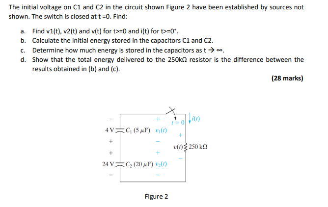
The initial voltage on C1 and C2 in the circuit shown Figure 2 have been established by sources not shown. The switch is closed at t =0. Find: a. Find v1(t), v2(t) and v(t) for t>=0 and i(t) for t>=0*. b. Calculate the initial energy stored in the capacitors C1 and C2. c. Determine how much energy is stored in the capacitors as t → ∞. d. Show that the total energy delivered to the 250k resistor is the difference between the results obtained in (b) and (c). (28 marks) 4VC₁ (5 μF) v₁(1) + + 24 V + C₂ (20 µF) ¹₂ (1) Figure 2 i(t) + v(t)}250 ΚΩ