Page 1 of 1
Q9. In the circuit shown below (Figure 9), there was an initial current in the inductor I₂ (0) = B [A]. The switch was c
Posted: Sun Jul 03, 2022 12:13 pm
by answerhappygod
- Q9 In The Circuit Shown Below Figure 9 There Was An Initial Current In The Inductor I 0 B A The Switch Was C 1 (93.21 KiB) Viewed 20 times
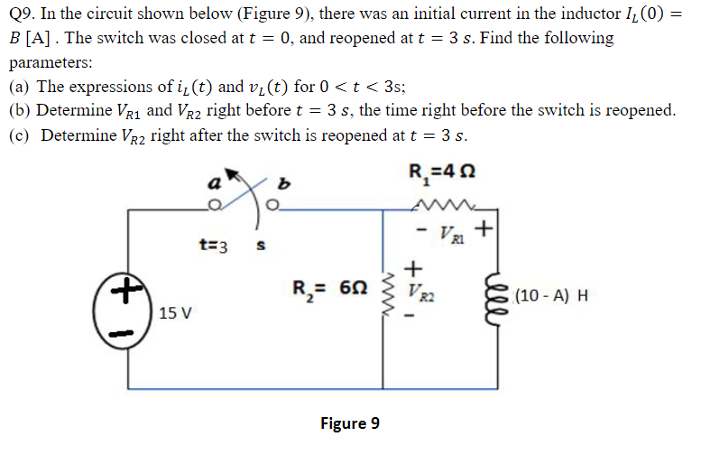
Q9. In the circuit shown below (Figure 9), there was an initial current in the inductor I₂ (0) = B [A]. The switch was closed at t = 0, and reopened at t = 3 s. Find the following parameters: (a) The expressions of i, (t) and v₁ (t) for 0 < t < 3s; (b) Determine VR₁ and VR2 right before t = (c) Determine VR2 A 1) right after the switch is reopened at t = 3 s. R₁=402 15 V 3 s, the time right before the switch is reopened. t=3 S R₂ = 60 Figure 9 - VRI + www. I VR2 + illl (10 - A) H