Page 1 of 1
2. Consider the circuit shown in the following Figure. The cut-in voltage of each diode is VDO = 0.7 V. (a) Let v₁ = (5+
Posted: Sun Jul 03, 2022 12:09 pm
by answerhappygod
- 2 Consider The Circuit Shown In The Following Figure The Cut In Voltage Of Each Diode Is Vdo 0 7 V A Let V 5 1 (39.98 KiB) Viewed 19 times
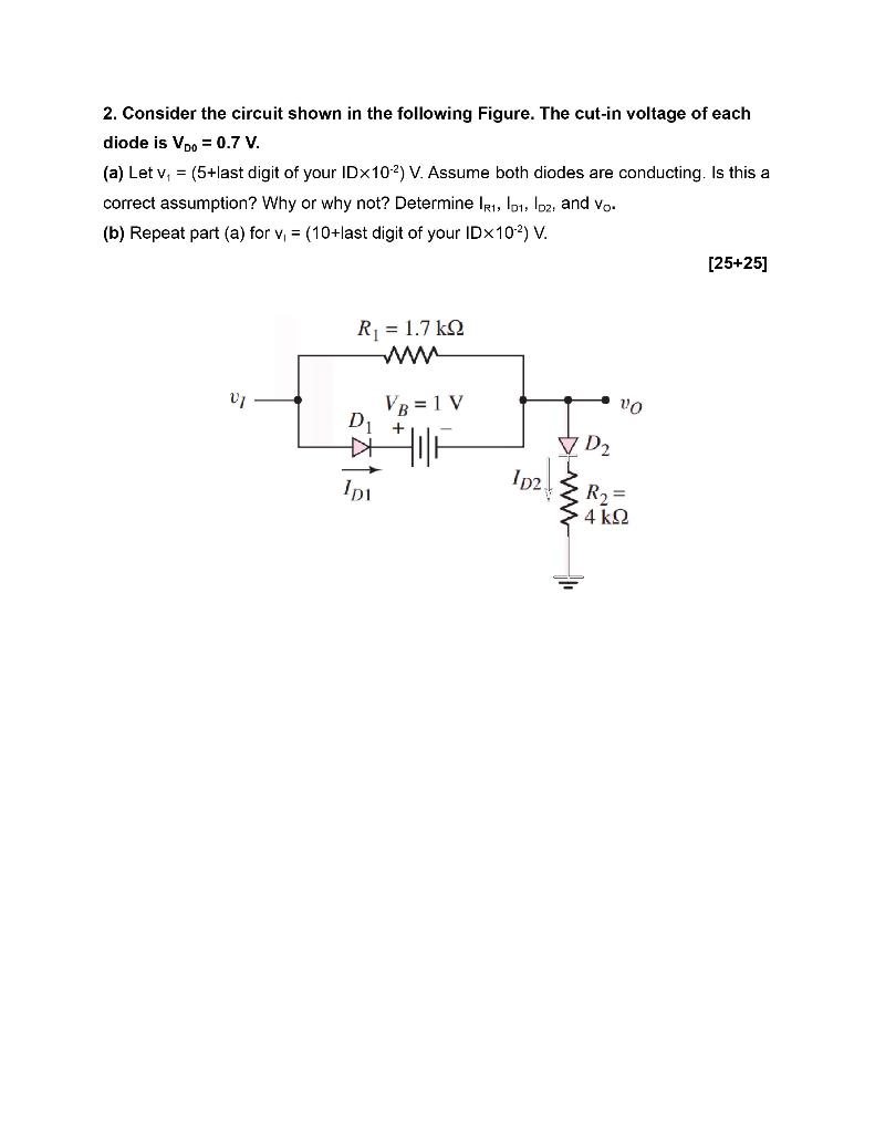
2. Consider the circuit shown in the following Figure. The cut-in voltage of each diode is VDO = 0.7 V. (a) Let v₁ = (5+last digit of your IDx102) V. Assume both diodes are conducting. Is this a correct assumption? Why or why not? Determine IR1, D1, D2, and vo. (b) Repeat part (a) for v₁ = (10+last digit of your IDX10²) V. VI R₁ = 1.7kQ VB = 1 V D₁ + 山 IDI Ip2. ✓ D₂ VO R₂ = 4kQ2 [25+25]