Page 1 of 1
Consider the following logic diagram then: 1. Write the Boolean expression for output x in the following figure. Determi
Posted: Sun Jul 03, 2022 12:08 pm
by answerhappygod
- Consider The Following Logic Diagram Then 1 Write The Boolean Expression For Output X In The Following Figure Determi 1 (27.94 KiB) Viewed 21 times
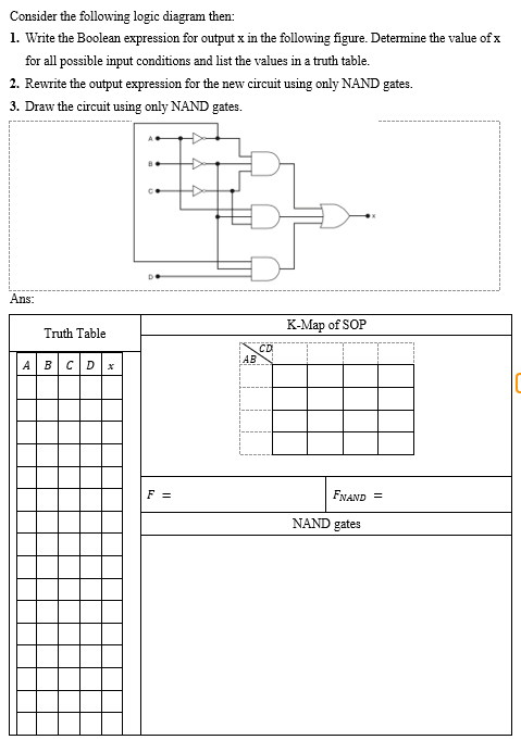
Consider the following logic diagram then: 1. Write the Boolean expression for output x in the following figure. Determine the value of x for all possible input conditions and list the values in a truth table. 2. Rewrite the output expression for the new circuit using only NAND gates. 3. Draw the circuit using only NAND gates. Ans: Truth Table A B C D x D. F = AB CD K-Map of SOP FNAND = NAND gates