Page 1 of 1
Figure 1 is a block diagram of a feedback control system. R(s) 2 (s + 1) 1 Figure 1 1 S Determine the system transfer fu
Posted: Fri Jul 01, 2022 7:24 am
by answerhappygod
- Figure 1 Is A Block Diagram Of A Feedback Control System R S 2 S 1 1 Figure 1 1 S Determine The System Transfer Fu 1 (91 KiB) Viewed 27 times
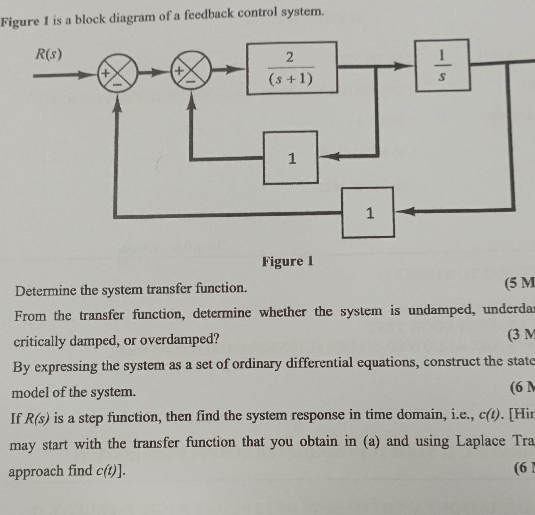
Figure 1 is a block diagram of a feedback control system. R(s) 2 (s + 1) 1 Figure 1 1 S Determine the system transfer function. (5 M From the transfer function, determine whether the system is undamped, underda critically damped, or overdamped? (3 M By expressing the system as a set of ordinary differential equations, construct the state model of the system. (6 M If R(s) is a step function, then find the system response in time domain, i.e., c(t). [Him may start with the transfer function that you obtain in (a) and using Laplace Traz approach find c(t)]. (6 M