Page 1 of 1
A mechatronics system could be represented through the block diagram represented in Figure Q2. Determine the values of g
Posted: Fri Jul 01, 2022 6:57 am
by answerhappygod
- A Mechatronics System Could Be Represented Through The Block Diagram Represented In Figure Q2 Determine The Values Of G 1 (31.71 KiB) Viewed 27 times
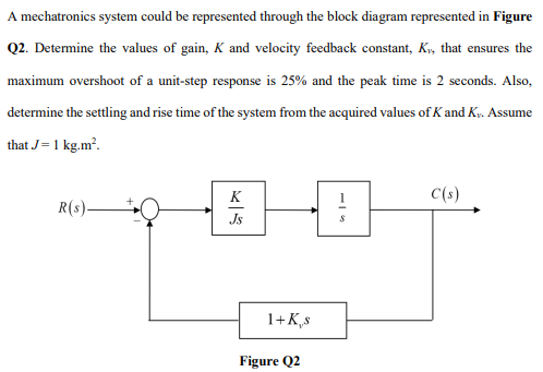
A mechatronics system could be represented through the block diagram represented in Figure Q2. Determine the values of gain, K and velocity feedback constant, K₁, that ensures the maximum overshoot of a unit-step response is 25% and the peak time is 2 seconds. Also, determine the settling and rise time of the system from the acquired values of K and Kr. Assume that J = 1 kg.m². R(s)- Js 1+ K,s Figure Q2 C(s)