- Question A B 4 20 Marks Demonstrate By Sketching How A 74138 Decoder In Figureq 4 A And Nand Gates Can Be Used To 1 (61.1 KiB) Viewed 26 times
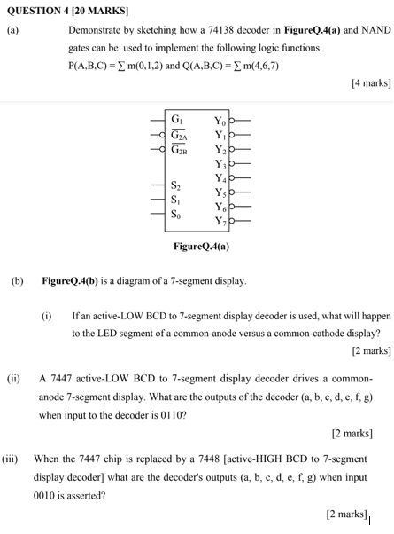
QUESTION (a) (b) 4 [20 MARKS] Demonstrate by sketching how a 74138 decoder in FigureQ.4(a) and NAND gates can be used to implement the following logic functions. P(A,B,C) = m(0,1,2) and Q(A,B,C) = m(4,6,7) 51515 G₁ G₂A G2B S₂ S₁ Yo Y₁ Y₂ Y3 Y4 Ys Y6 Y₁ FigureQ.4(a) FigureQ.4(b) is a diagram of a 7-segment display. [4 marks] (1) If an active-LOW BCD to 7-segment display decoder is used, what will happen to the LED segment of a common-anode versus a common-cathode display? [2 marks] (ii) A 7447 active-LOW BCD to 7-segment display decoder drives a common- anode 7-segment display. What are the outputs of the decoder (a, b, c, d, e, f, g) when input to the decoder is 0110? [2 marks] (iii) When the 7447 chip is replaced by a 7448 [active-HIGH BCD to 7-segment display decoder] what are the decoder's outputs (a, b, c, d, e, f, g) when input 0010 is asserted? [2 marks]
Cik X Q₁ (c) Circuits shown in FigureQ.4(c) has one input X and one output Z. Analyze the circuit and complete the timing diagram in Figure Q.4(d). The initial output for both flip-flops are 0 Q₂ Z X Clock DA SET e D g CLR QA (MSB) De SET Q b. CLR Q FigureQ.4(b) С FigureQ.4(c) Figure Q.4(d) Z [10 Marks] I