Page 1 of 1
QUESTION 5 Figure Q.5(a) and Figure Q.5(b) show the block diagram and the logic diagram of a 74293 integrated circuit ch
Posted: Fri Jul 01, 2022 6:16 am
by answerhappygod
- Question 5 Figure Q 5 A And Figure Q 5 B Show The Block Diagram And The Logic Diagram Of A 74293 Integrated Circuit Ch 1 (76.16 KiB) Viewed 28 times
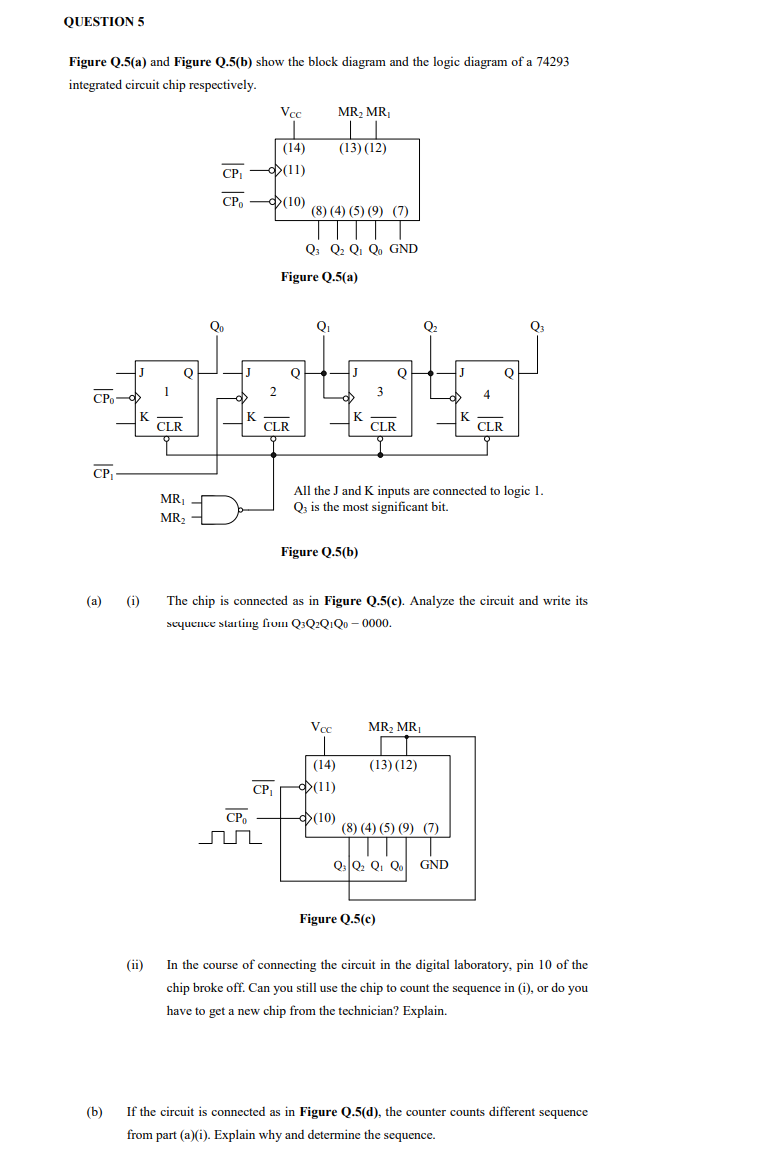
QUESTION 5 Figure Q.5(a) and Figure Q.5(b) show the block diagram and the logic diagram of a 74293 integrated circuit chip respectively. CPo CP₁ J K (a) (i) 1 CLR Q MR₁ MR₂ CP₁ CP K 2 CP₂ nr Vcc CP₁ (14) (11) (10) CLR Q Figure Q.5(a) (8) (4) (5) (9) (7) TTT Q3 Q₂ Q1 Qo GND Q₁ MR₂ MR₁ (13) (12) Vcc J Figure Q.5(b) (14) (11) (10) K 3 CLR 0 All the J and K inputs are connected to logic 1. Q3 is the most significant bit. The chip is connected as in Figure Q.5(c). Analyze the circuit and write its sequence starting from Q3Q2Q1Q0 - 0000. MR₂ MR₁ Q₂ (13) (12) (8) (4) (5) (9) (7) Figure Q.5(c) J Q3 Q₂ Q₁ Qo GND K CLR 0₂ (ii) In the course of connecting the circuit in the digital laboratory, pin 10 of the chip broke off. Can you still use the chip to count the sequence in (i), or do you have to get a new chip from the technician? Explain. (b) If the circuit is connected as in Figure Q.5(d), the counter counts different sequence from part (a)(i). Explain why and determine the sequence.