Page 1 of 1
2. A simple power system shown in Figure 7 consists of two synchronous machines connected through three phase transforme
Posted: Fri Jul 01, 2022 6:15 am
by answerhappygod
- 2 A Simple Power System Shown In Figure 7 Consists Of Two Synchronous Machines Connected Through Three Phase Transforme 1 (49.79 KiB) Viewed 31 times
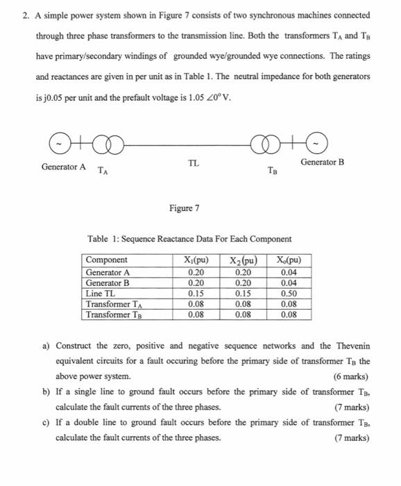
2. A simple power system shown in Figure 7 consists of two synchronous machines connected through three phase transformers to the transmission line. Both the transformers T₁ and TB have primary/secondary windings of grounded wye/grounded wye connections. The ratings and reactances are given in per unit as in Table 1. The neutral impedance for both generators is j0.05 per unit and the prefault voltage is 1.05 20° V. ото Generator A TA TL Component Generator A Generator B Line TL Transformer T Transformer TB Figure 7 Table 1: Sequence Reactance Data For Each Component X₂ (pu) 0.20 0.20 0.15 0.08 0.08 X₁(pu) 0.20 CO+G TB 0.20 0.15 0.08 0.08 Generator B X.(pu) 0.04 0.04 0.50 0.08 0.08 a) Construct the zero, positive and negative sequence networks and the Thevenin equivalent circuits for a fault occuring before the primary side of transformer To the above power system. (6 marks) b) If a single line to ground fault occurs before the primary side of transformer TB, calculate the fault currents of the three phases. (7 marks) c) If a double line to ground fault occurs before the primary side of transformer TB. calculate the fault currents of the three phases. (7 marks)