Page 1 of 1
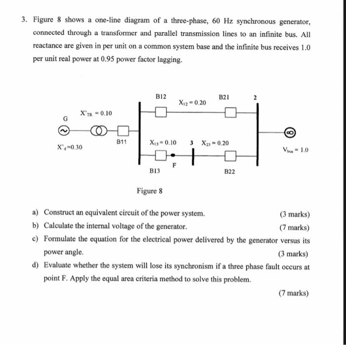
3. Figure 8 shows a one-line diagram of a three-phase, 60 Hz synchronous generator, connected through a transformer and
Posted: Fri Jul 01, 2022 6:15 am
by answerhappygod
- 3 Figure 8 Shows A One Line Diagram Of A Three Phase 60 Hz Synchronous Generator Connected Through A Transformer And 1 (44.99 KiB) Viewed 29 times
3. Figure 8 shows a one-line diagram of a three-phase, 60 Hz synchronous generator, connected through a transformer and parallel transmission lines to an infinite bus. All reactance are given in per unit on a common system base and the infinite bus receives 1.0 per unit real power at 0.95 power factor lagging. X'TR = 0.10 X'=0.30 B11 B12 B13 X12 = 0.20 X₁3= 0.10 3 X₂10.20 + F B21 B22 2 BO V1.0 Figure 8 a) Construct an equivalent circuit of the power system. (3 marks) b) Calculate the internal voltage of the generator. (7 marks) c) Formulate the equation for the electrical power delivered by the generator versus its power angle. (3 marks) d) Evaluate whether the system will lose its synchronism if a three phase fault occurs at point F. Apply the equal area criteria method to solve this problem. (7 marks)