Page 1 of 1
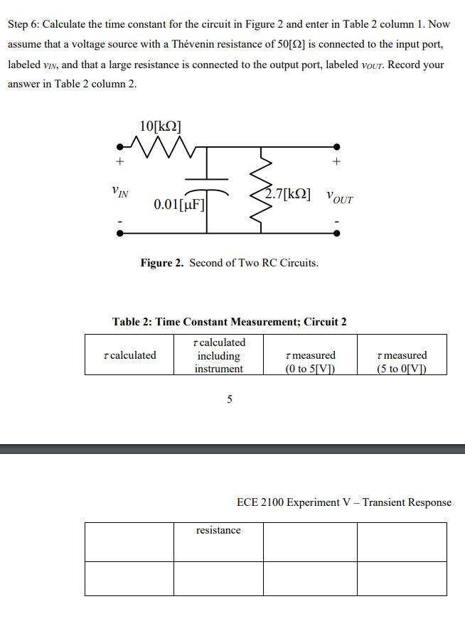
Step 6: Calculate the time constant for the circuit in Figure 2 and enter in Table 2 column 1. Now assume that a voltage
Posted: Fri Jul 01, 2022 6:15 am
by answerhappygod
- Step 6 Calculate The Time Constant For The Circuit In Figure 2 And Enter In Table 2 Column 1 Now Assume That A Voltage 1 (52.25 KiB) Viewed 38 times
Step 6: Calculate the time constant for the circuit in Figure 2 and enter in Table 2 column 1. Now assume that a voltage source with a Thévenin resistance of 50[2] is connected to the input port, labeled VIN, and that a large resistance is connected to the output port, labeled vour. Record your answer in Table 2 column 2. VIN 10[ΚΩ] W NT 0.01 [uF] Figure 2. Second of Two RC Circuits. T calculated Table 2: Time Constant Measurement; Circuit 2 7 calculated including instrument 1.7[k] YOUT 5 resistance T measured (0 to 5[V]) 7 measured (5 to 0[V]) ECE 2100 Experiment V - Transient Response