Page 1 of 1
An automatic printing machine as shown in Figure Q3(a)(i) is widely used in advanced manufacturing industries. Based on
Posted: Fri Jul 01, 2022 6:14 am
by answerhappygod
- An Automatic Printing Machine As Shown In Figure Q3 A I Is Widely Used In Advanced Manufacturing Industries Based On 1 (60.4 KiB) Viewed 31 times
- An Automatic Printing Machine As Shown In Figure Q3 A I Is Widely Used In Advanced Manufacturing Industries Based On 2 (33.15 KiB) Viewed 31 times
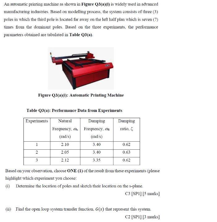
An automatic printing machine as shown in Figure Q3(a)(i) is widely used in advanced manufacturing industries. Based on modelling process, the system consists of three (3) poles in which the third pole is located far away on the left half plan which is seven (7) times from the dominant poles. Based on the three experiments, the performance parameters obtained are tabulated in Table Q3(a). Figure Q3(a)(i): Automatic Printing Machine Table Q3(a): Performance Data from Experiments Experiments Natural Frequency. (rad/s) 2.10 2.05 2.12 1 2 3 Damping Frequency, (rad/s) 3.40 3.40 3.35 Damping ratio, 0.62 0.63 0.62 Based on your observation, choose ONE (1) of the result from these experiments (please highlight which experiment you choose: (1) Determine the location of poles and sketch their location on the s-plane. C3 [SP1] [5 marks] (ii) Find the open loop system transfer function, G(s) that represent this system. C2 [SP1] [3 marks]
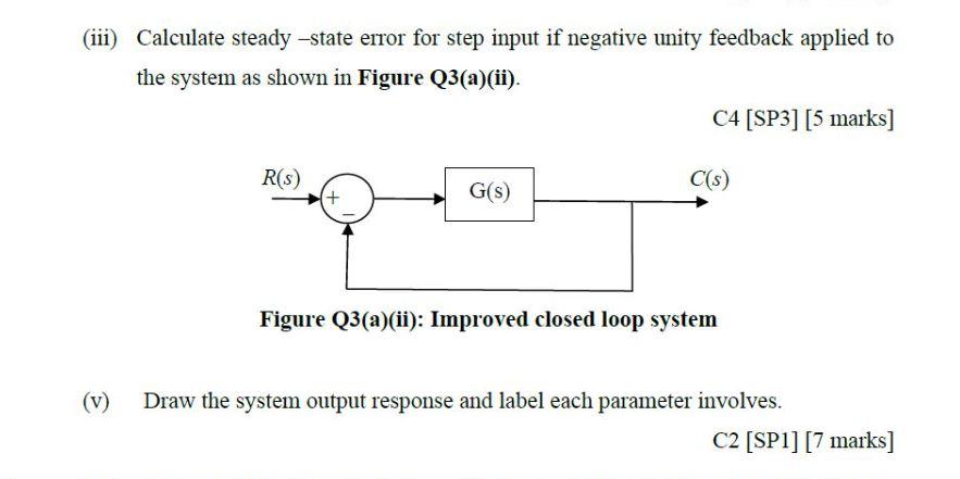
(iii) Calculate steady-state error for step input if negative unity feedback applied to the system as shown in Figure Q3(a)(ii). R(S) + G(s) C4 [SP3] [5 marks] C(s) Figure Q3(a)(ii): Improved closed loop system Draw the system output response and label each parameter involves. C2 [SP1] [7 marks]