Page 1 of 1
(c) The load line and Q-point of the circuit in Figure Q3(c)(i) is shown in Figure Q3(c)(ii). For the transistor, ß = 12
Posted: Fri Jul 01, 2022 6:14 am
by answerhappygod
- C The Load Line And Q Point Of The Circuit In Figure Q3 C I Is Shown In Figure Q3 C Ii For The Transistor Ss 12 1 (26.75 KiB) Viewed 35 times
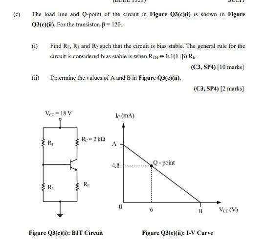
(c) The load line and Q-point of the circuit in Figure Q3(c)(i) is shown in Figure Q3(c)(ii). For the transistor, ß = 120. (i) (ii) Find R₁, R₁ and R₂ such that the circuit is bias stable. The general rule for the circuit is considered bias stable is when RTH = 0.1(1+B) RE. (C3, SP4) [10 marks] Determine the values of A and B in Figure Q3(c)(ii). Vcc=18 V R₁ R₂ Re=2 k RE Figure Q3(c)(i): BJT Circuit Ic (mA) A 4.8 0 Q-point (C3, SP4) [2 marks] B Figure Q3(c)(ii): I-V Curve VCE (V)