Page 1 of 1
A translational mechanical control system is as shown in Figure Q2(b). (i) (ii) f(0) +X₂ (1) k₂ = 2N/m 0000 fv₁ = 2N-s/m
Posted: Fri Jul 01, 2022 6:14 am
by answerhappygod
- A Translational Mechanical Control System Is As Shown In Figure Q2 B I Ii F 0 X 1 K 2n M 0000 Fv 2n S M 1 (41.02 KiB) Viewed 42 times
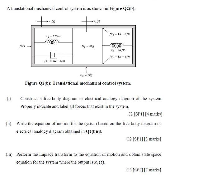
A translational mechanical control system is as shown in Figure Q2(b). (i) (ii) f(0) +X₂ (1) k₂ = 2N/m 0000 fv₁ = 2N-s/m M₂- Akg M₂ - 2kg f₂ IN 8/m 0000 k₂ - 3N/m -IN-s/m Figure Q2(b): Translational mechanical control system. Construct a free-body diagram or electrical analogy diagram of the system. Properly indicate and label all forces that exist in the system. C2 [SP1] [4 marks] Write the equation of motion for the system based on the free body diagram or electrical analogy diagram obtained in Q2(b)(i). C2 [SP1] [3 marks] (iii) Perform the Laplace transform to the equation of motion and obtain state space equation for the system where the output is x₂ (t). C3 [SP2] [7 marks]