Page 1 of 1
A feedback system is shown in Figure 2. The desired transient response characteristics of the system when subject to a u
Posted: Fri Jul 01, 2022 6:11 am
by answerhappygod
- A Feedback System Is Shown In Figure 2 The Desired Transient Response Characteristics Of The System When Subject To A U 1 (54.26 KiB) Viewed 21 times
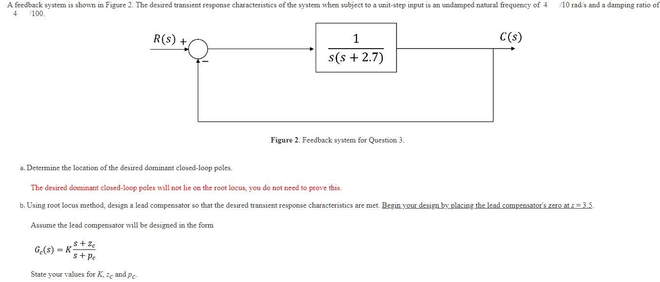
A feedback system is shown in Figure 2. The desired transient response characteristics of the system when subject to a unit-step input is an undamped natural frequency of 4 4 /100. R(S) + Ge(s) = K 1 s(s+ 2.7) Figure 2. Feedback system for
Question 3. C(s) /10 rad/s and a damping ratio of a. Determine the location of the desired dominant closed-loop poles. The desired dominant closed-loop poles will not lie on the root locus, you do not need to prove this. b. Using root locus method, design a lead compensator so that the desired transient response characteristics are met. Begin your design by placing the lead compensator's zero at s = 3.5. Assume lead compensator will be designed in the form s+ Zc s + pc State your values for K, zc and pc-